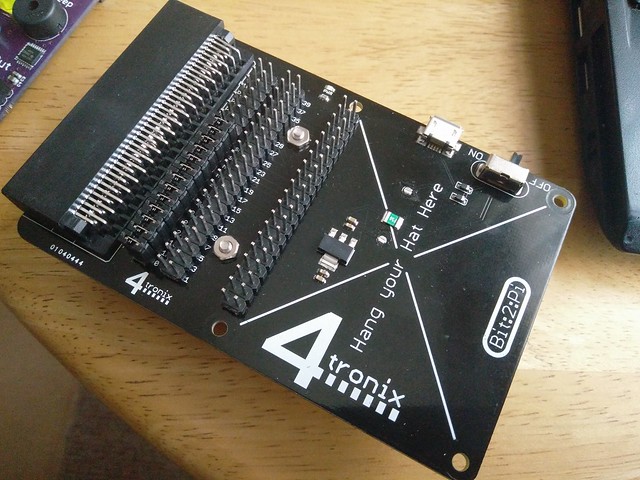
Bit:2:Pi
Gareth at 4Tronix is a genius. He produces lots of wonderful boards for the Raspberry Pi, codebug and micro:bit.
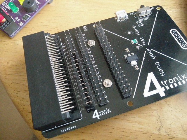
One of his latest boards is Bit:2:Pi which is a little different to other micro:bit boards...in that it enables the connection of add on boards made for the Raspberry Pi.
So what did I do?
Well being me I like to make silly little projects. They are quick, fun and help me to understand how things work.
So my challenge for this project was to control a micro gear metal motor, connected to the Pibrella, using a micro:bit. I wanted the motor to slowly increase its speed until it hit maximum, and then slowly decelerate to 0. All at the push of a button on the micro:bit.
So what equipment did I use?
- A micro:bit with micro USB cable
- Bit:2:Pi
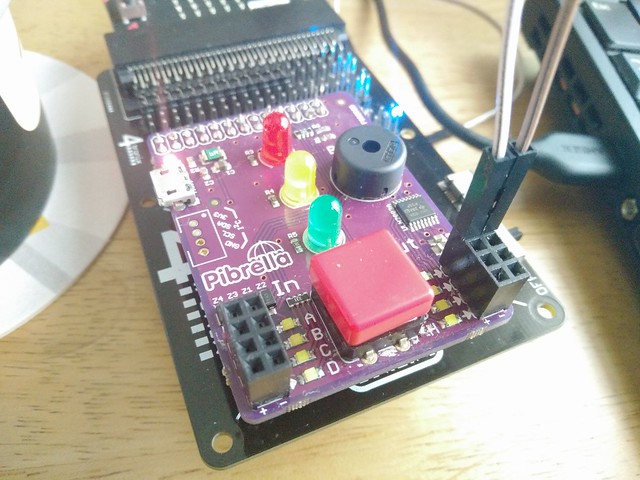
- Pibrella
- 2 x Female to Male jumper wires
- Micro gear metal motor (with soldered shim on the back
- 3 x AA batteries to provide extra power to the Bit:2:Pi for the motor.
- Blu tack / modelling clay to keep the motor from running around the table.
- Laptop running the Mu Python editor. Download Mu here
Assemble the kit
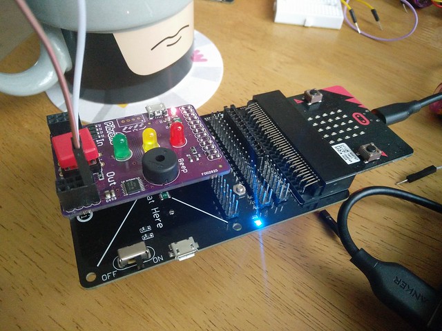
Building the hardware is simple.
Your micro:bit fits into the top of the Bit:2:Pi, and the Pibrella attaches to the GPIO pins at the bottom of the board.
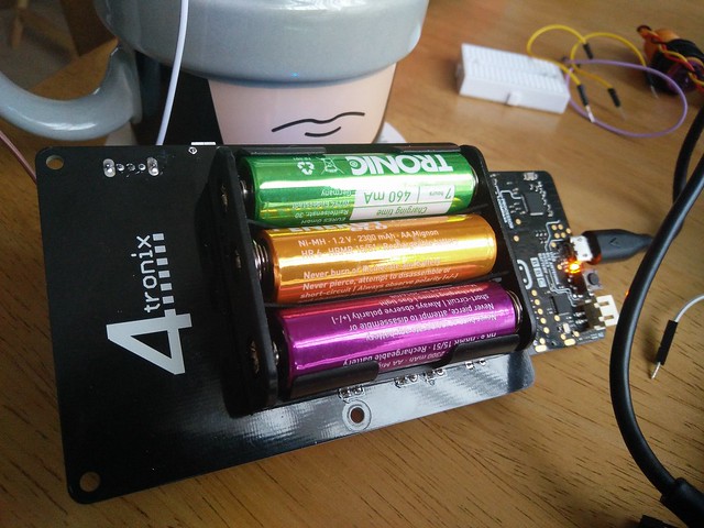
Insert the batteries into the underside of the Bit:2:Pi.
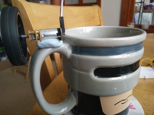
Robocup optional extra
Then all you need to do is attach the motor to the connections for output e.
Now connect your micro:bit to your computer and ensure that the On switch in selected on the Bit:2:Pi, as we will need the power later.
Bit:2:Pi Pin references
The Bit:2:Pi provides a connection between certain GPIO pins used with the Raspberry Pi add on board, and all of the GPIO pins for the micro:bit.
The connections are as so.
|
Micro:Bit Pin |
GPIO Pin |
Physical Pin |
|
0 |
04 |
7 |
|
1 |
17 |
11 |
|
2 |
18 |
12 |
|
8 |
27 |
13 |
|
12 |
22 |
15 |
|
16 |
23 |
16 |
|
5 |
24 |
18 |
|
11 |
25 |
22 |
|
13 |
SCL |
5 |
|
14 |
MISO |
21 |
|
15 |
MOSI |
19 |
|
19 |
SCLK |
23 |
|
20 |
SDA |
3 |
Using Phil's great pinout.xyz website I can find the pins which are used by Pibrella
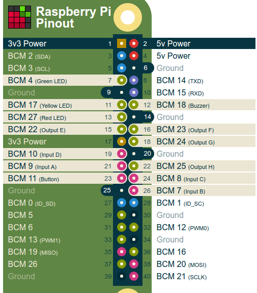
Output E is on pin 22 (BCM reference) so using the table above I can see that it is mapped to pin 12 on the micro:bit. So now that I know this I can start my silly project.
Software
Installing Mu is really straightforward, and once opened you should see a screen similar to this.
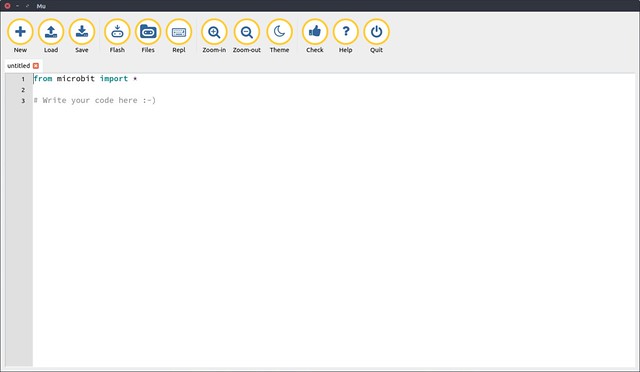
The Mu interfaceis beautifully simple, and we shall write some code in this window.
Our first line is to import the micro:bit library.
from microbit import *
Then I create an infinite loop to run the code forever!
while True:
But what do I want to run forever? Well I want to check that the user has pressed button B on the micro:bit.
if button_b.was_pressed():
If button B has been pressed then I want to use a for loop and a range, to repeat the loop until it reaches the end of the range. Each time the loop goes round, the value of i is increased by 1.
for i in range(1024):
So each time the loop goes round, i increases in vale by 1, but what do we use it for? Well each time the loop goes round we write a new value to pin 12, which is connected to output e of the Pibrella...phew!
The analog value increases each time the loop goes round, and slowly the motor will come to life before reaching it's top speed.
pin12.write_analog(i)
To control the pace of the loop, and to stop the motor running off the table at top speed straight away, we add a sleep(10) but what does the 10 mean? Well the sleep function uses milliseconds instead of seconds, so 1 second is really 1000ms. So to slow the loop down we sleep for a hundredth of a second (0.01s) or 10ms
sleep(10)
Lastly we print the value of i to the Python shell for debug purposes.
print(i)
We now add the slowdown part of the code, this is exactly the same as the previous loop, but it works in reverse.
Our for loop works in reverse, starting at 1023 and counting down to 0 in increments of -1.
        for i in range(1023,0,-1):
            pin12.write_analog(i)
            sleep(10)
            print(i)
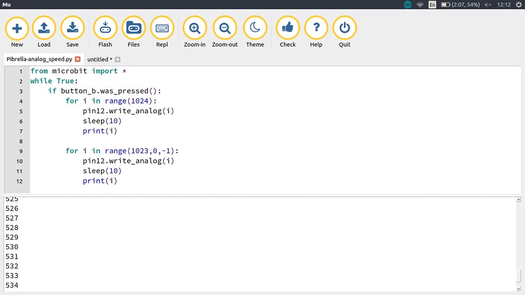
Complete Code Listing
Here is all of the code for this project.
from microbit import *
while True:
    if button_b.was_pressed():
        for i in range(1024):
            pin12.write_analog(i)
            sleep(10)
            print(i)

        for i in range(1023,0,-1):
            pin12.write_analog(i)
            sleep(10)
            print(i)
Flash the code
You'll see the Flash button on the menu, with your micro:bit connected to your computer, click on this to send the code to the micro:bit.
After a few seconds the code will be written. But before you test the code, make sure that you click on Repl to open the Python shell at the bottom of the screen. Here we can see the output of the code, especially the print(i) that we added in the loops to tell us that the code is working.
Test it!
When ready press button B on your micro:bit and you will hear the motor turn on, grumble for a few seconds...and then roar to life!
Conclusion
Bit:2:Pi is lots of fun! It can be used with a number of different Raspberry Pi boards, I even had a dabble with the Unicorn pHAT from Pimoroni...super bright LED blinkies!
If you have a micro:bit and a Raspberry Pi then this is an ideal board to share accessories.
Enjoy hacking with this board!