Traditional Christmas Neopixel Project 2017 Node-RED Edition!
Get a coffee, put your feet up as this is a long one!
A short time ago...in a street not so far away....
For 2016 I decorated our window with lots of neopixels
Neopixel Christmas lights! pic.twitter.com/Rdyx47I8HI
— biglesp (@biglesp) December 10, 2016
But for 2017 I wanted to do something a little different. So I dug around in my bits box and found these...
And then I looked at our tree and thought
Our Christmas tree needs to glow with the light of a thousand suns!
And so the project for 2017 was born.
Stop messing around and give me details!
Ok, so this project uses a Raspberry Pi Zero W running the latest version of Raspbian. Using Node-RED we shall create a web interface that enables any device on the network to control the colour of the lights on the tree. The project should use one single power supply and take steps to ensure best practices.
For this project you will need
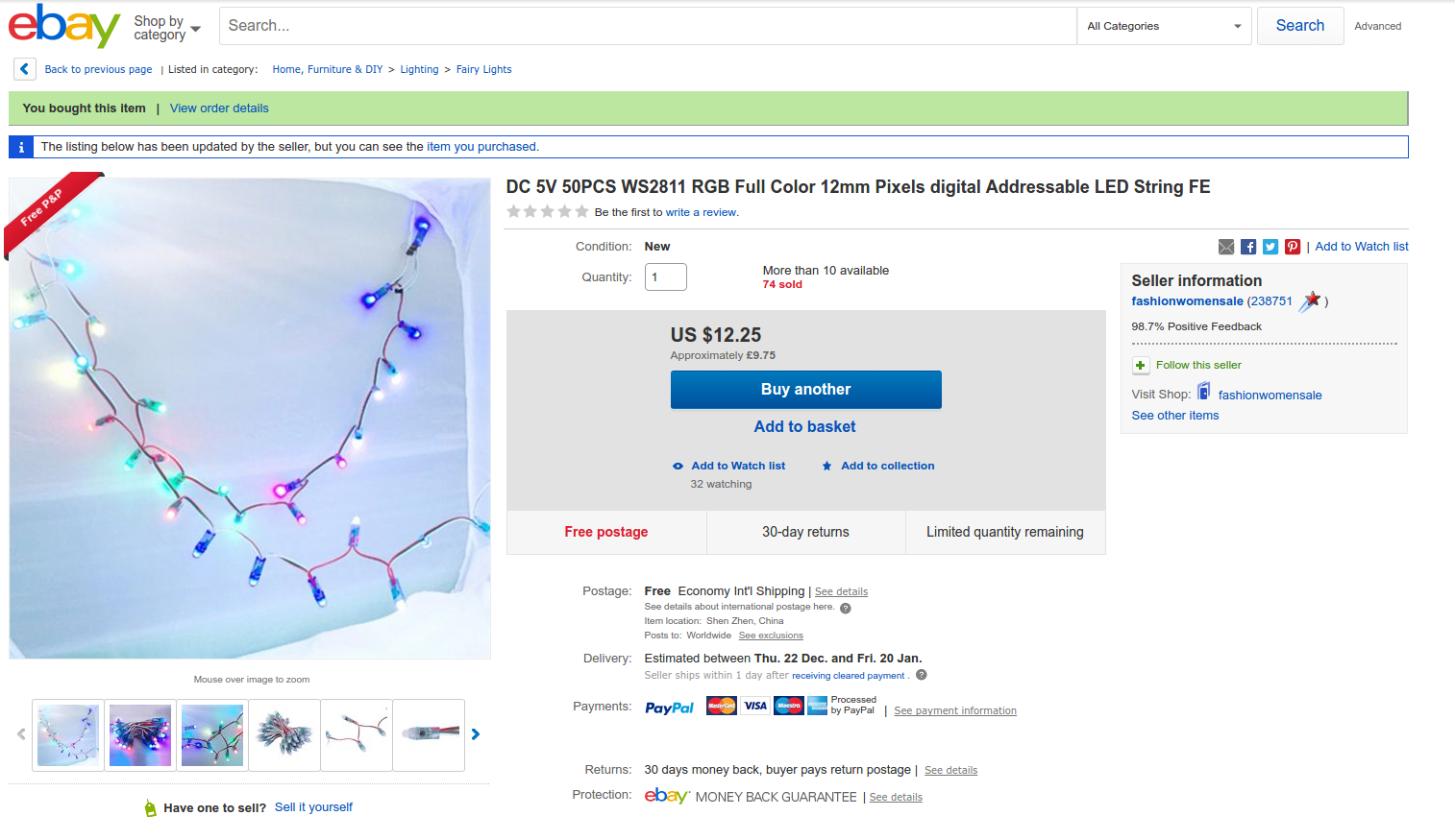
- WS2811 RGB Full Color 12mm DC 5V LED String
- A Raspberry Pi Zero W
- The latest version of Raspbian
- An Internet connection
- A 470 Ohm Resistor (Yellow, Purple, Brown, Gold)
- A 1000uf capacitor
- A protozero board
- A 5V 4A power supply
- A Female DC Barrel Jack Connector
- 2 x Screw Terminals
- Wire
- Soldering iron and equipment
Building the circuit
There is quite a bit of work to do for this project, so starting with the hardware is the logical place to begin.
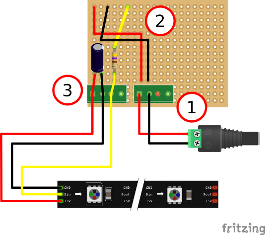
- Power comes into the board from the 5V 4A power supply connected via the barrel jack, to the screw terminals. The 5V (Red) wire and the GND (Black) wires are secured in the screw terminals.
- From the screw terminals, use some new wires and the 5V (Red) wire is soldered to the 5V pin of the Pi Zero W using the ProtoZero board. The GND (Black) wire is soldered to the GND pin of the Pi Zero W using the ProtoZero board.
- Using more wire, solder a wire from the 5V (Red) wire at 1. to the positive leg of the capacitor. Using more wire solder the GND connection from 1. to the negative leg of the capacitor. This means our pixels share the same power source as the Pi, but they have a capacitor to protect them. A 470 Ohm resistor should be connected between GPIO18 and the third screw terminal.
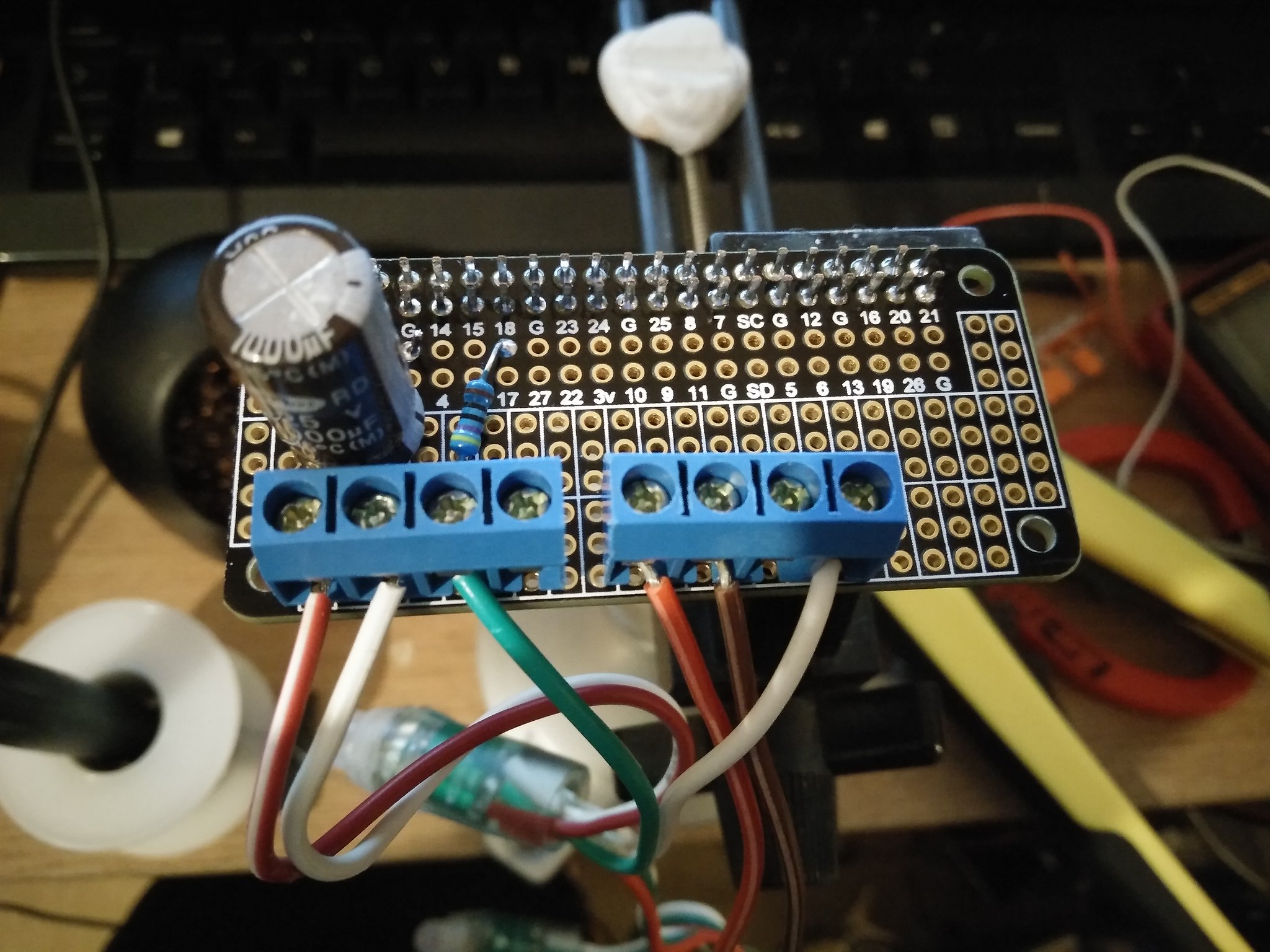
I used a ProtoZero board, designed to sit atop the Raspberry Pi Zero W GPIO.
So now is the time to solder all 40 of those pins, you know you want to! (Remember to solder the board so the white PROTOZERO text is on the underside...not on top like I once did.) As you can see in the image, there are two sets of screw terminals. The left set of four screw terminals (3.) are used to connect the neopixels to the board (From left to right 5V, GND, Data) The 5V and GND pins are connected to a 1000uf capacitor to ensure that the onrush of current to the pixels is smooth, and the data pin is connected to GPIO18 of our Raspberry Pi Zero W via a 470 Ohm resistor (2.) as this reduces the chance of a spike on our data line.
To the right of the board are another set of four screw terminals (1.) (Left to right, 5V, GND, SPARE, SPARE but with a spare ground connection secured to stop it flapping around and causing a short) these are from our power input. The 5V connection is also made to the 5V pin of the Pi, and to the positive leg of the capacitor. The GND pin is also connected to GND of the Pi and the negative leg of the capacitor. So now my Pi Zero W is powered from the same source as my neopixels will be, but the neopixels will draw their power via the capacitor.
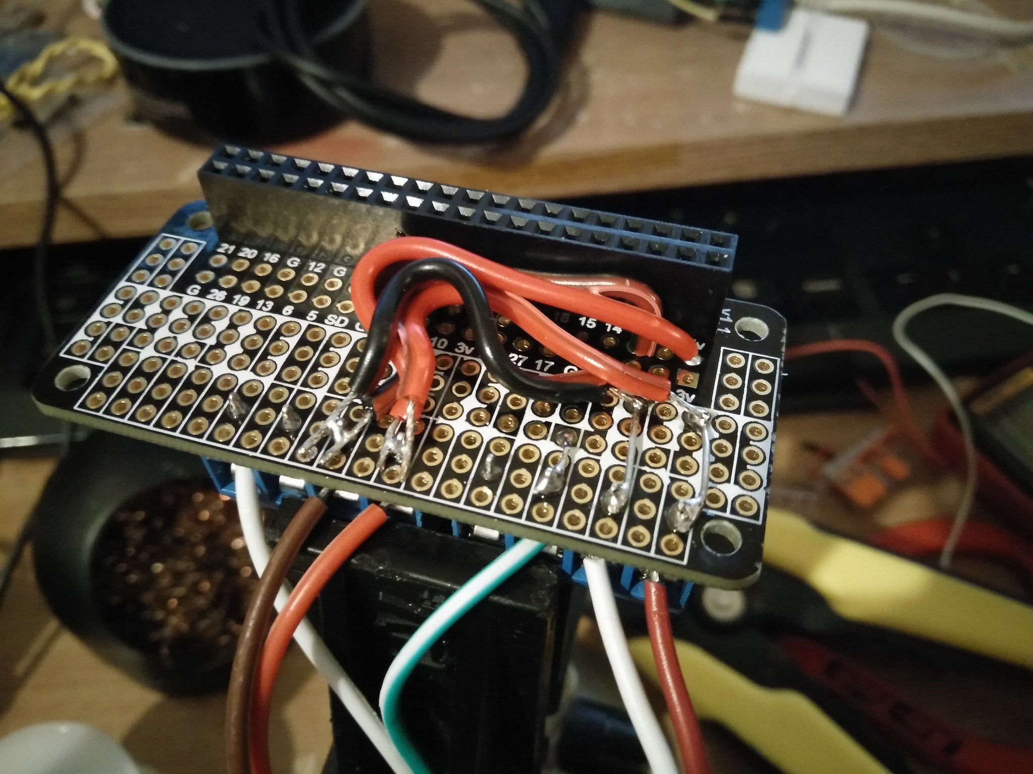
My wiring to connect 1. to 3. looks like this, don't worry I used a little hot glue to hold the wires down.
Not sure on the best practice for neopixels, WS2811 WS2182B LEDs? Then I refer to the Adafruit uberguide :)
So now all we need to do is connect our board to a Pi Zero W, and then connect our neopixels and power supply, oh and of course, keyboard, mice etc!
Software Build
Boot up your Pi and head to the desktop!
We shall be using Node-RED for this project and it is already bundled with Raspbian, but first we need to install the Node Package Manager (npm), so open a terminal and enter the following command.
sudo apt update && sudo apt install npm
Now this may take some time, but once completed, stay in the terminal.
Installing packages for Node-RED
Now that npm is installed we can use it to install packages for Node-RED. These packages are extra functionality that doesn't come as standard with Node-RED. But in order to install the packages, we need to be in our node-red directory, and that is found in our home directory. So type the following to go there.
cd /home/pi/.node-red/
Now that we are in there, we can now install two packages. The first creates a dashboard interface, a web user interface, for our project.
npm i node-red-dashboard
The second package handles our neopixels, specifically providing us with nodes with which we can control them in Node-RED.
npm i rpi-neopixels
Installing the neopixel driver
Our last configuration step is to install a driver than enables our code to talk to the neopixels, and this driver comes from Pimoroni and their fab Unicorn HAT range of boards. They have even given us a one line installer to make it easy. Enter this into the terminal and it will run the installer.
\curl -sS https://get.pimoroni.com/unicornhat | bash
The Node-RED bit...finally
Congrats, you've made it this far, hang in there!
Lets set Node-RED to start on boot, in the terminal type the following to create a service that will run in the background.
sudo systemctl enable nodered.service
Now reboot to ensure that the service is working correctly. Get back to the Raspbian desktop before moving onwards.
Then open a web browser and point it to 127.0.0.1:1880 this opens the web interface for the Node-RED editor.
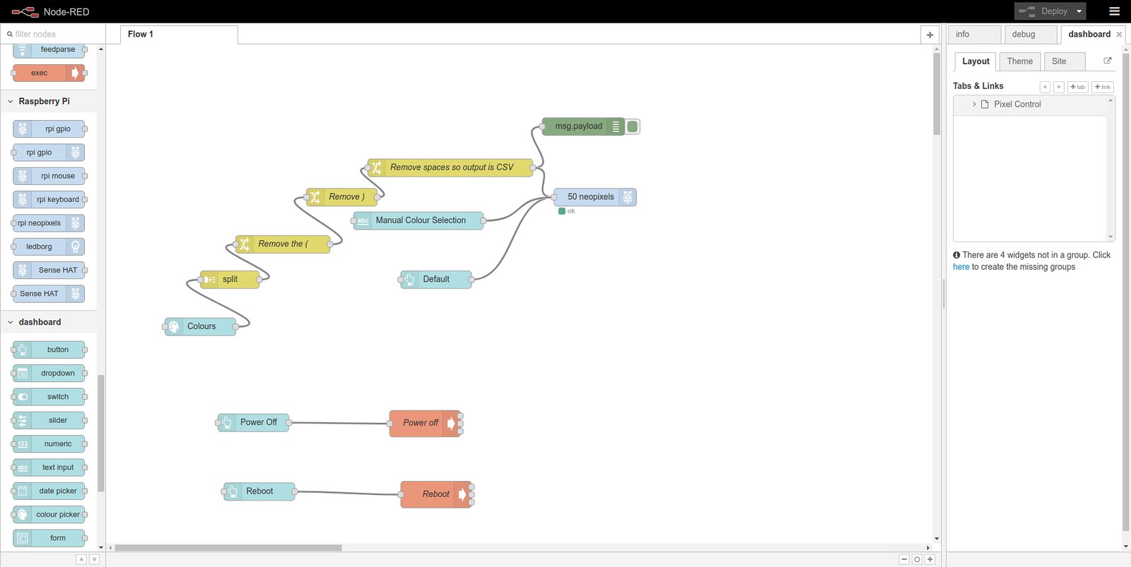
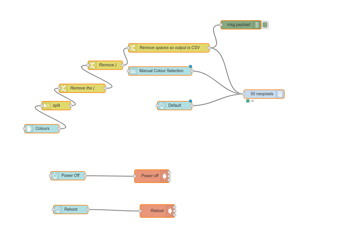
Our goal is to create this flow, which takes a colour, then goes through a series of "filters" to remove unwanted data. This is then passed to the 50 Neopixels node, and to the Debug tab. So our first port of call is to create a new user interface, called a dashboard there is a tab called this in the top right, click on it.
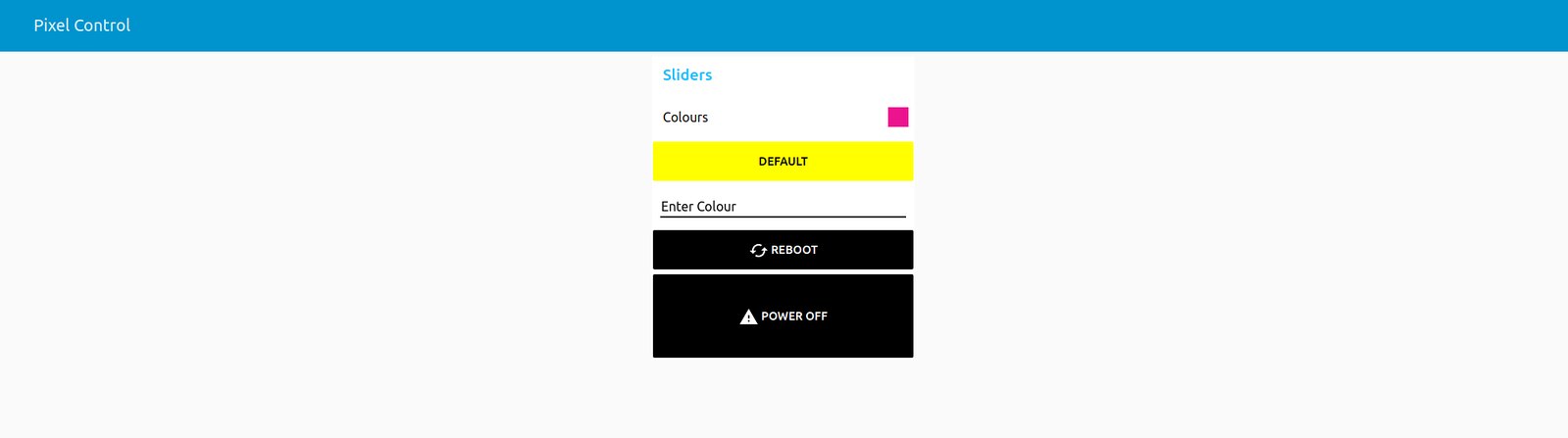
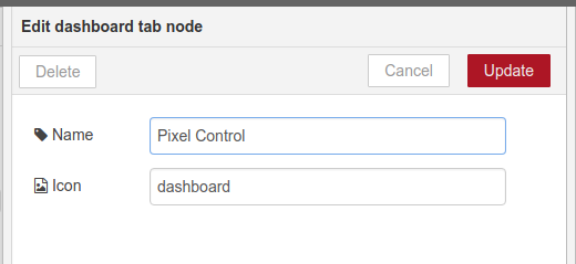
Now click on + tab to create a new layout. Give it a name then save / update, I chose Pixel Control as the name for my interface.
Now lets create a new group, a place where all of the content that makes our dashboard can be laid out ready for the user. I called it sliders as originally I used three sliders to control the RGB values, but since then (yeah this post has taken a few weeks to research and test) I have moved on. Click on +group to create a new group and name it accordingly.
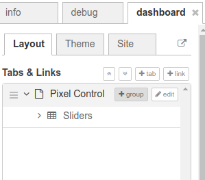
Dashboard complete! Now lets start creating the flow!
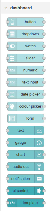
The first node to use is the colour picker node from the dashboard section. Drag it into Flow 1
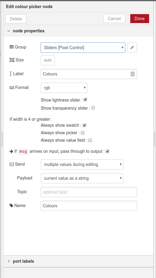
Double click on the colour picker node and change the config to match the following.
Now we need to do a little tinkering with the output from that node as it sends data as an RGB (Red, Green, Blue) string with preceding text.
"rgb(rrr,ggg,bbb)"
But what we want is...
(rrr,ggg,bbb)
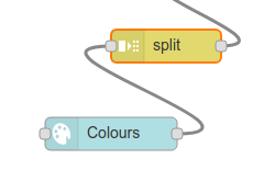
So we use a split node found in the function section. Drag it into Flow 1.
Join the colour picker node to this node by connecting the grey dots (from the colour picker drag from the right grey dot, to the left grey dot of the split node, this will connect the output of the first node, to the input of the second.)
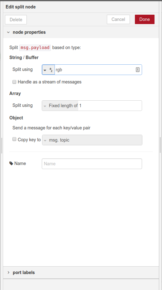
Now lets configure the split node, we need it to remove the "rgb" portion of the output. Set your config as follows. Then click Done.
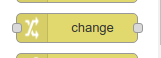
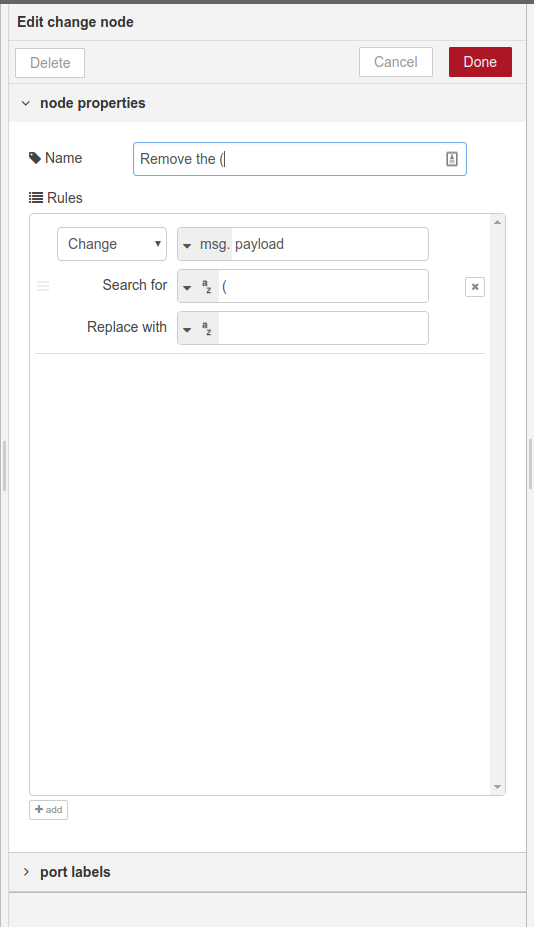
The next two nodes are very similar, they handle removing the opening and closing parenthesis brackets. For this we use a change node to change the "(" into nothing so it essentially removes the brackets. Change is found in the function section.
The first change to make is to remove the ( from the output and we do that as follows.
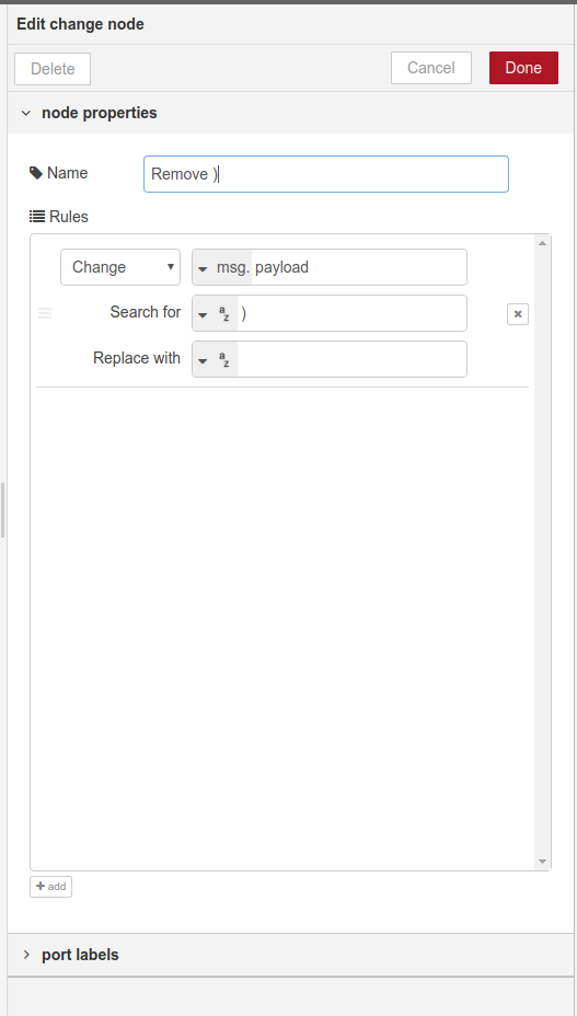
Then we need another change node and this second change node will remove the closing ) from the output.
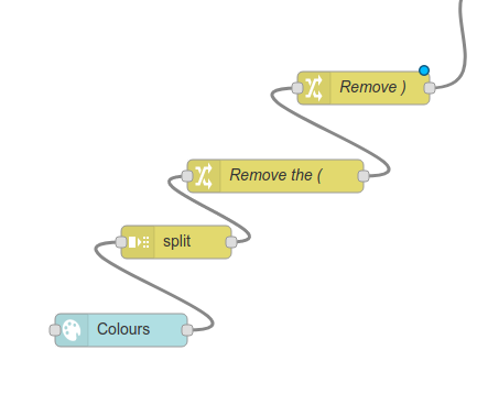
Progress Update
You should now have something that looks like this.
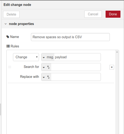
The last manipulation is another change node, this time it searches for all the spaces in the output, and replaces them with no spaces. So the search for field has one spacebar press in the field. The Replace with field has no key pressed inside of it.
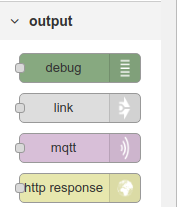
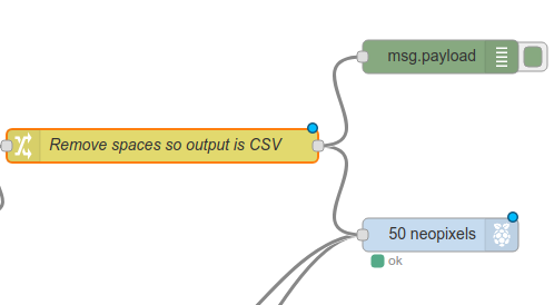
Carrying on, we now need to send the output of all this manipulation to two outputs. The first is to send the output to the debug tab, on the right of the screen. The debug node is in the output section. Drag it into the flow and connect its input to the previous nodes output.
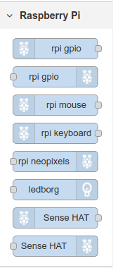
The next node is our rpi neopixels node, found in the Raspberry Pi section. This node enables us to control the neopixels using the manipulated input.
Drag the rpi neopixels node into the flow and connect its input to the output of the Remove spaces so output is CSV node.
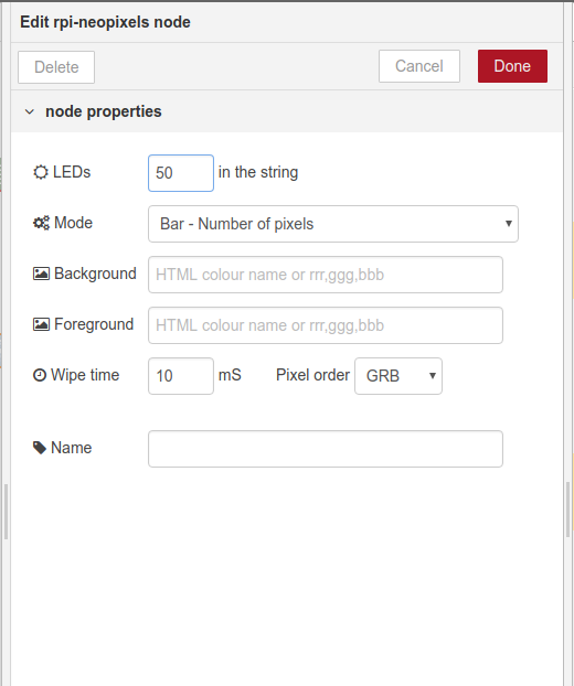
Lets edit the rpi neopixel node so that it
- Confirms the number of LEDs in the string, I had 50
- Mode is Bar - Number of pixels.
- Wipe time is 10 milliseconds
- Pixel Order was GRB for me, but this may need a little trial and error for you.
Give it a test!
Ok now we can click on Deploy in the top right of the screen. This will save our code and run it. Your pixels should light up and check their RGB levels (i.e BRIGHT!)
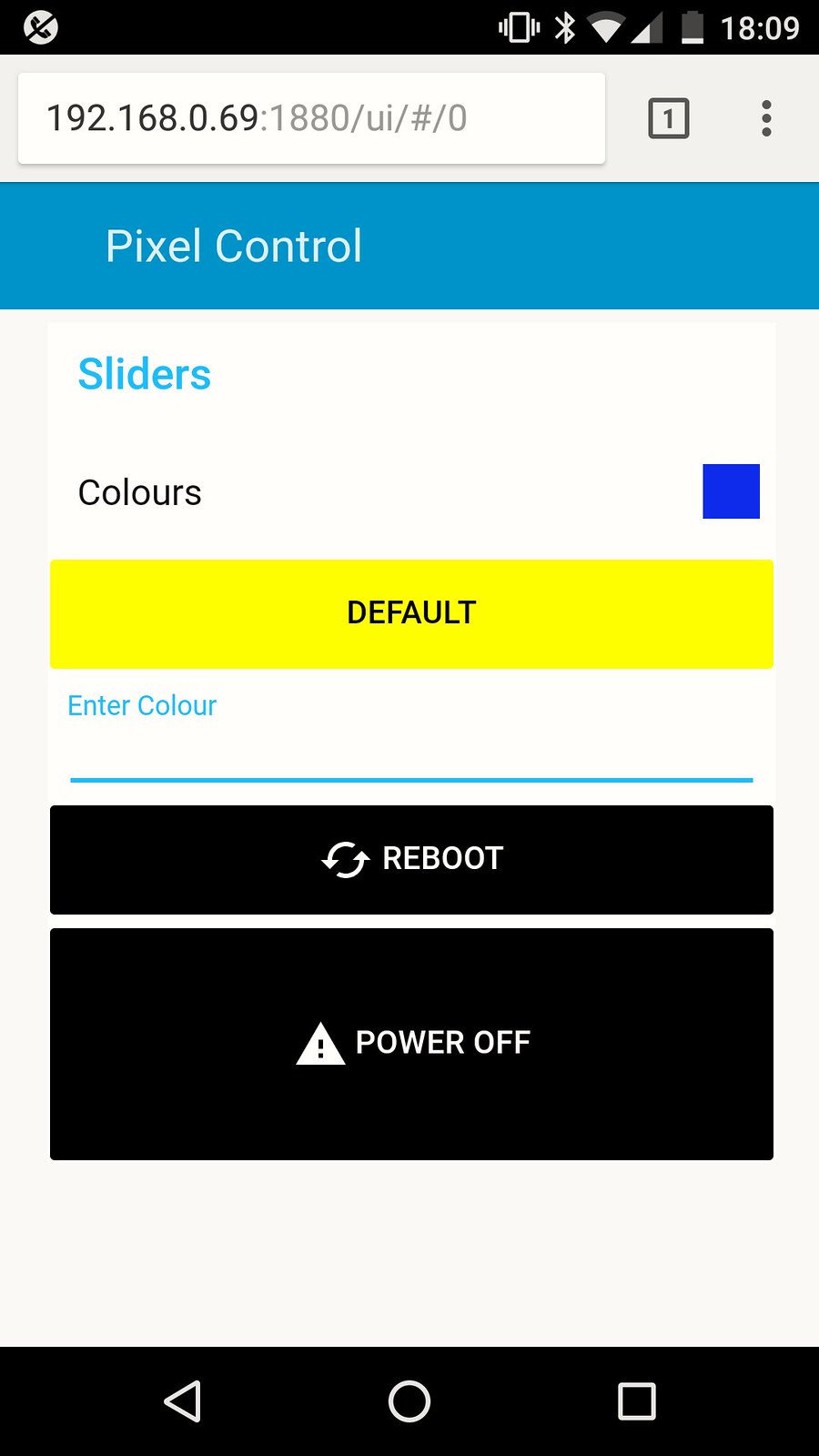
Open a new browser tab and go to 127.0.0.1:1880/ui where you will see the user interface that we have created for this projectand you will see "Colours" and a grey box next to it. Click on the box top open the colour picker. Now single click on a colour and the pixels will change to that colour.
RESULT!
Taking it further?
Manual Colour Input
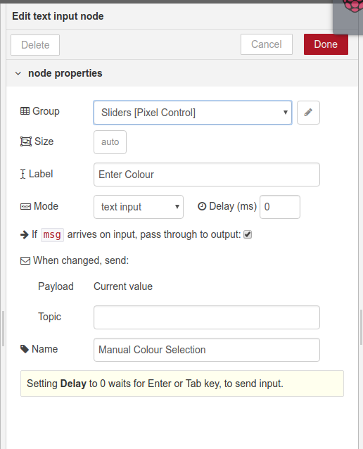
I love the colour picker but sometimes I want to manually type the colour in so from the dashboard section I chose the text input node, dragging it into the flow.
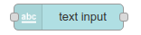
Then double click on the text input node and configure as follows.
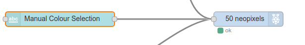
Next join the output of the text input node to the input of the 50 neopixels node.
Click on Deploy and then go back to the user interface 127.0.0.1:1880/ui and enter a manual colour, for example red is 255,0,0 then press Enter
The pixels will change colour accordingly!
Default Colour
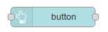
MrsP has a particular colour scheme in mind for the tree this year, and part of the deal I made to use neopixels on the tree was that I would be able to reproduce that colour. So when MrsP wants that colour, she can simple choose it as the default. So I made a button to do just that. From the dashboard section drag the button node into the flow.
Double click on the button node and edit it So that the colour and background are set to a colour of your choosing. I chose black text on a yellow background. The payload is the output produced when the button is clicked, in this case it is the RGB values for a shade of gold / yellow that MrsP wants on the tree.
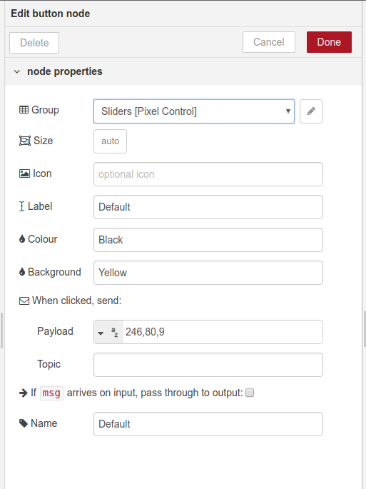
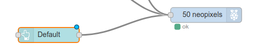
When ready join the output of this node to the input of the 50 neopixels node.
Click on Deploy and then go back to the user interface 127.0.0.1:1880/ui and click on the Default button. Your lights will change to that colour!
You've made a Node-RED controlled, Raspberry Pi powered strings of neopixels!!!
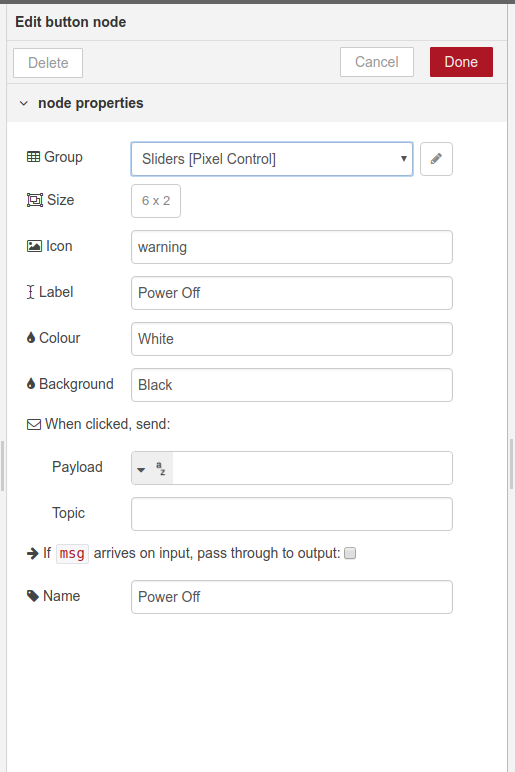
Power Control
If there is a problem, then you may need to reboot your Pi, or at the end of the night turn off the Pi safely so that the SD card is not corrupted. For this we shall use two more buttons from the dashboard section. Call the first Power Off and edit the settings as follows.
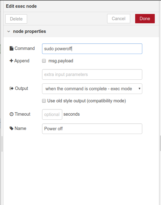
The output of our button press is blank, as the next node, called exec
will use the blank input as a trigger to run a command on the underlying Raspbian system. Drag an exec block into the flow and connect it to the Power off node.
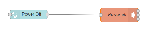
Edit the exec node so that it runs the command sudo poweroff.
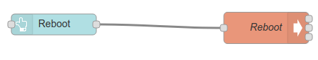
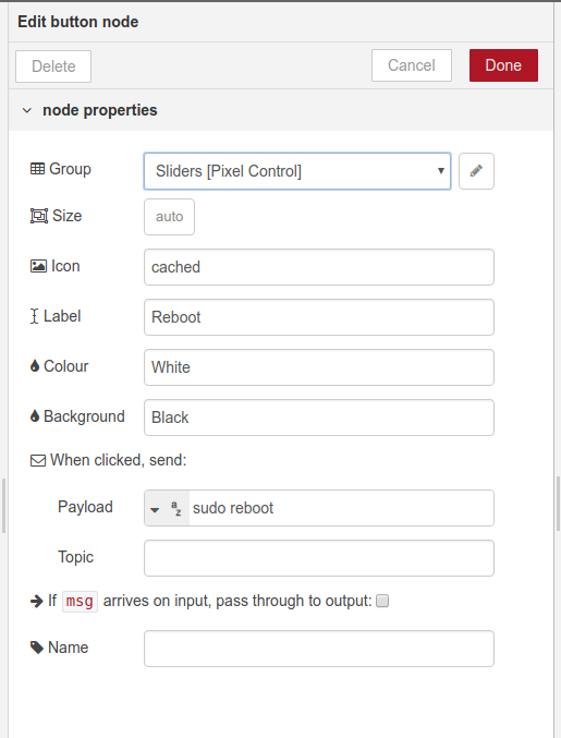
Now do the same for the reboot option.
All of the flows that make up this project should look like this...
Now is the time to Deploy and test the new buttons in the web interface. First test the reboot option. A full reboot cycle will take a few minutes as the Pi Zero W is not as quick as other Pis. When rebooted, go back to the user interface 127.0.0.1:1880/ui and then click on Power off to test that it successfully shuts down the Pi.
With those tests complete, our final step is to create a static IP for the Pi Zero W. So power up the Pi and go to the Raspbian desktop. Right click on the WiFi icon and select Wireless and wired network settings and set the Interface to wlan0 and then configure the IPv4 address and Router to match your network.
Reboot the Pi and test that it has a static IP address by typing the following into a terminal.
hostname -I
You should see the IP address that you specified.
Now go to your mobile / tablet / laptop and visit that IP address, followed by :1880/ui
For example I set my IP address to 192.168.0.69 so on my mobile I visited 192.168.0.69:1880/ui and saw this...