Friday Fun - ATtiny85 £10 Robot Challenge!
Can we build a robot for less than £10? - Well nearly! Originally this blog post did build a robot for just under £10 (£9.88) but there were a few quirks which required addressing. Chiefly this was the robot only worked 1/6 times. The issue was traced, after a lengthy Twitter discussion, to be the shared power supply. So I have modified the project to use two power sources, but this means we are over budget, by a few £. Update below!!
Thanks to everyone for their support and help while tracking this issue down. Remember: It is ok to FAIL (First Attempt In Learning), I failed a few times making this project. But I learnt a great deal along the way!
Update 3/4/2019 We have a single power source!
Many thanks to Gareth at 4tronix, we now have a solution to the power issues. By using a 10Ω resistor on each connection from the L9110S to the motor, we can limit the current used by the motors and stop the reset bug! I shall update this post to show this.
ATtiny85 robot running from a single 3x AAA battery pack! Thanks to @4tronix_uk for the debug help. I shall update the blog post https://t.co/UU5r66mV8k to show the added resistors&the cost. Again many thanks to @4tronix_uk So if you are at #PiWars today,say thanks on my behalf. pic.twitter.com/WrC6xqXkgW
— biglesp (@biglesp) March 31, 2019
Why?
This post started off as a challenge to myself.
Could I build a robot using the ATtiny85 and make it as cheap as possible?
So with the challenge in mind I set to it and the result is this blog post. I really wanted to get this under £10 but because I needed two power supplies, I went over budget by 62p.
We are back under budget!
It attracted a little interest!
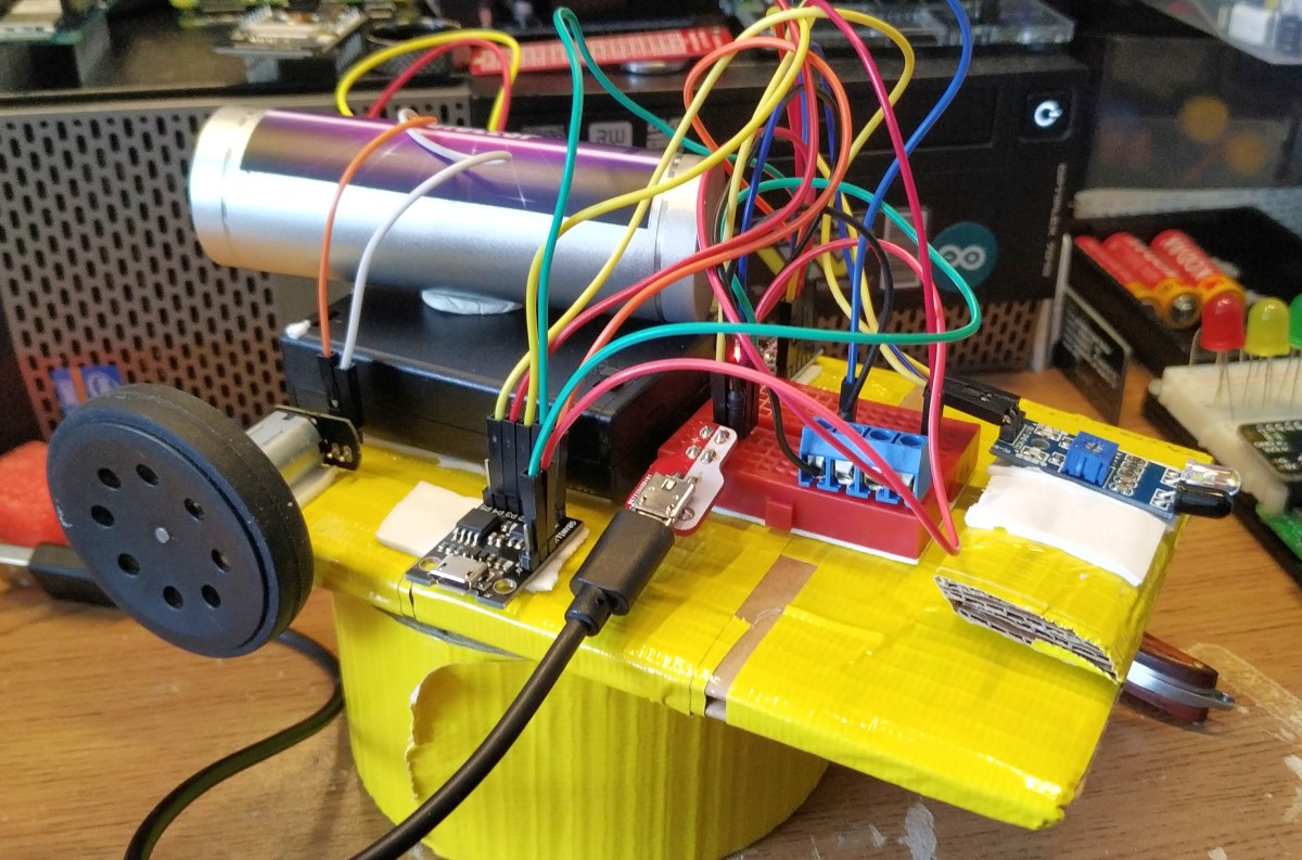
Here is the working prototype, still in a "test rig" (on an upside down breadboard held together with blutack.)
Ooh my #fridayfun tutorial research is going well! Here I show a working ATtiny85 powered robot that costs <£10 to buy and it can be coded using the @arduino application. Ditched the ultrasonic sensor for a much simpler IR obstacle sensor. pic.twitter.com/2NJ4vZ8oKf
— biglesp (@biglesp) March 20, 2019
First successful two motor test after a confusing couple of hours!
So I finally have working code! Pins 4 & 5 are a bit iffy, but it was user error all along. Thanks to everyone who offered suggestions and support. pic.twitter.com/M4w0uifkiI
— biglesp (@biglesp) March 19, 2019
Yay I made the motor move!
Testing motor control with an ATtiny85 via an L9110S motor controller. All coded using the @arduino IDE pic.twitter.com/9w6KuKzjbI
— biglesp (@biglesp) March 19, 2019
What do we need to build a robot?
- A Computer with the latest Arduino IDE installed
- An ATtiny85 90p
- An L9110S Motor Controller 38p
- InfraRed Obstacle Sensor 30p
- 2 x 6V DC motors £1.59 each
Micro USB breakout power adapter 58p + 19p delivery (77p)USB Battery £1 (Poundland)- Battery holder for 3 x AAA batteries 74p
- Jumper wires (mixture of Male to Female, Male to Male and Female to Female) £1.46 for all three kinds. Second image next to Color
- A Chassis for the robot and a caster front wheel for balance (milk bottle lid), cardboard / plastic yogurt pots etc. FREE from your recycling.
- 2 x Wheels £1.46 for 4! These can be proper wheels, or discs cut from cardboard.
- A breadboard 43p
- 10Ω Resistors, pack of 100 45p
Total cost: £10.62 so just over budget! £9.30!!
So why don't we build one together?!
Get your fresh code here!
All of the code and circuit diagram for the project is in my GitHub repo. You are free to download and use it all.
Here is a link to a ZIP archive with everything inside.
Setting up the ATtiny85
We will start by setting up the Arduino IDE so that we can use the ATtiny85. This requires a few steps but fear not!

The code for the ATTiny85 is written using the Arduino IDE, so open the application and before we write any code we need to ensure that we have our ATtiny85 listed as a usable board.
To do this click on File >> Preferences and in the new dialog box look for the Additional Board Manager URLs and look for the overlapping windows icon to the right. Click on this and paste the following URL into the new window. Then press Ok.
http://digistump.com/package_digistump_index.json

So now we can add the ATtiny85 to our list of boards. Go to Tools >> Board >> Boards Manager and wait for a few seconds until the list of boards has been updated. Once you have control, in the top right of the screen use the search box and search for digispark and then install the board. The final step before we start coding is to tell Arduino what board we are using, so go back to Tools >> Board and select Digispark (Default - 16.5mhz). And with that done we can start writing the code!
Writing the code for our robot
The Arduino language is based upon C and chances are that if you are reading this then you have dabbled with some coding (Python, Ruby etc) and while the Arduino code may look a little different, trust me it is rather simple if we break it down.
Functions
In programming a function can be thought of as grouping code so that we can execute all the lines when we call the name of the function.
A real world example of a function is when we ask someone to make a cup of tea. The name of the function is "make_a_cup_of_tea" and inside that function are all the steps to make a cup of tea.
In Arduino we create functions by first declaring the name of the function, this is how we will use it.
The word
voidindicates that the function is expected to return no information to the function from which it was called. We can replacevoidwithintif our function returned an integer.
Our first function is called forward and as you can guess it makes the robot move forward.
void forward(){
The next two lines inside the function are comments. Arduino / C uses // for single line comments. We use comments to explain our code so that others can read it.
  //Forward
  //Motor A
To control the pins on the ATtiny85 we need to turn them on or off and for that we use the command digitalWrite followed by the number of the pin, and then whether we turn the pin on (HIGH) or turn the pin off (LOW). In the next two lines we turn pins 0 and 1, on and off respectively. This controls Motor A to move forward.
  digitalWrite(0, HIGH);
  digitalWrite(1, LOW);
The other motor, Motor B needs to rotate in the opposite direction as the motor is mounted on the other side of the robot. So for pins 2 and 3 we set them to LOW and HIGH respectively as the wiring from the L9110S motor controller is already set to enable the motor to spin the opposite direction.
  //Motor B
  digitalWrite(2, LOW);
  digitalWrite(3, HIGH);
}
So that is the first function completed, we can move forward, but how do we move backward? Well by creating another function called reverse and inside the function we reverse the HIGH and LOW for the pins so that they are the opposite value to those used in forward. Copy the code from forward and rename the function to reverse like so.
void reverse(){
  //Reverse
  //Motor A
  digitalWrite(0, LOW);
  digitalWrite(1, HIGH);
  //Motor B
  digitalWrite(2, HIGH);
  digitalWrite(3, LOW);
}
Now lets write a function to spin the robot left. To spin the robot we need to turn one motor forward, and the other reverse. To spin left we need to turn Motor A forwards, and Motor B backwards.
void left(){
  //Spin Left
  //Motor A forwards
  digitalWrite(0, HIGH);
  digitalWrite(1, LOW);
  //Motor B backwards
  digitalWrite(2, HIGH);
  digitalWrite(3, LOW);
}
And just like before, in order to move in the opposite direction, in this case spin right, we need to reverse the HIGH and LOW that we used in left. Copy the left function and rename it to right and change the HIGH and LOW to match.
void right(){
  //Spin Right
  //Motor A backwards
  digitalWrite(0, LOW);
  digitalWrite(1, HIGH);
  //Motor B forwards
  digitalWrite(2, LOW);
  digitalWrite(3, HIGH);
}
The final function to control our robot is called stop and as you can guess this function is used to stop our robot. This function will set every motor pin to LOW and it will stop the motors turning.
void stop(){
  //All motors off
  //Motor A stop
  digitalWrite(0, LOW);
  digitalWrite(1, LOW);
  //Motor B stop
  digitalWrite(2, LOW);
  digitalWrite(3, LOW);
}
The next part of the code is a built in Arduino function called setup and it is used to setup the pins that we will use to control the motors and for our IR obstacle sensor. Pins that are used to control a component, for example the motors, are outputs where as the pin that connects to the IR sensor is an input. Using pinMode we tell the Arduino code about each pin, and whether it is an input or output.
void setup() {
  // put your setup code here, to run once:
  pinMode(0, OUTPUT);
  pinMode(1, OUTPUT);
  pinMode(2, OUTPUT);
  pinMode(3, OUTPUT);
  pinMode(4, INPUT);
}
The final part of the code!
In this last section we are in another built in function, this time it is called loop and this is the code that will continuously run...in a loop! To start we add a 500 miliseconds delay to our code. This gives our sensor time to settle each time the loop goes round.
void loop() {
  // put your main code here, to run repeatedly:
  delay(500);
Now on to reading the IR obstacle sensor and for this we need to use a conditional test which simply asks a question...
Has the robot got too close to an object?
Our IR obstacle sensor sends IR light towards an object, and using the trim potentiometer (blue plastic box on the board) we can change the distance using a screwdriver. Typically they are set to 10cm but we can tinker. Give it a go! If there is nothing in the way then the pin we are using for the sensor (pin 4, which is an input) will be set to 1 (HIGH / On) and that means we are safe to move forward. If the sensor detects something < 10cm away then the pin is set to 0 (LOW / Off) and that means the answer to our question is yes there is something in the way. This is how we ask the question using a condition test in Arduino.
if (digitalRead(4) == 0) {
So what happens if the robot detects an object? We call our left function to spin the robot to the left and we set the delay to 200 milliseconds which should be enough to spin the robot a little to the left.
    left();
    delay(200);
But what happens if the answer to the question...
Has the robot got too close to an object?
Is no? Well the next few lines handle that. This is called else and this part of the code is activated if the first condition (our question) is False / No. This means that our robot is happy to move forward and continue driving. So we call the forward function and create a 1 second delay which means our motor will be on for 1 second.
  } else {
    forward();
    delay(1000);
  }
}
So there is our code, click on File >> Save and name the code ATtiny85-Robot
Flash the code!
With the code completed we can now go click on the Upload button (it is an arrow pointing to the right) or we can go to Sketch >> Upload both do the same job. This will trigger the compile, check and upload process. If you look at the black bar at the bottom of the Arduino IDE you will see lots of text whizz past, but then it will stop and ask you to plug in the ATtiny85 like so...
Running Digispark Uploader...
Plug in device now... (will timeout in 60 seconds)
Connect your ATtiny85 to a micro USB lead and then plug in the USB lead to your computer. The Arduino IDE will detect the board and will start uploading the code to it.
Once done you can unplug the ATtiny85 from the computer, and remove the micro USB lead from the ATtiny85 as now we need to build the project.
Shouldn't we have built the circuit before loading the code? Well no, I noticed a little quirk when testing. Sometimes the board would not upload the code correctly and would either error or hang. So I removed all the connections and every flash since has been fine!
Wiring the circuit

Above is the complete circuit for this project. As you can see there are a lot of wires, but lets break the circuit down and work with it section by section.
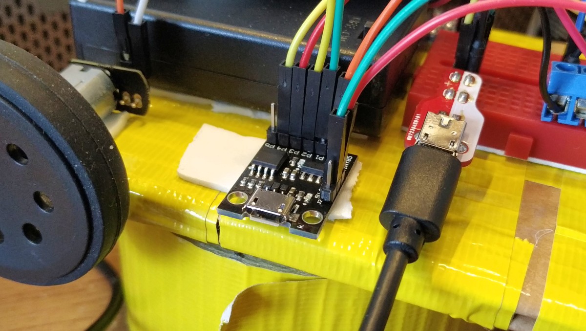
Connecting Power to the ATtiny85

The ATtiny85 can be powered in two ways. Via the (micro) USB port or via the VIN (Voltage In) pin. Make sure that the voltage is 5V. As we are using a single power supply, the AAA batteries, we can connect them directly to the VIN pin of the ATtiny85.
Powering the Sensor

Our IR sensor is powered from the single power source via the breadboard which we are using to distribute the power. The GND pin of the sensor is connected to the commond GND connection for all components.
Powering the Motors
Our motors are powered using the single power source, our 3 x AAA battery pack. The red wire, VCC connects to the VCC pin on the L9110S via a female to female jumper wire. The black wire, GND connects to the commond GND connection for all components.
Controlling the Motors
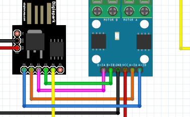
The ATtiny85 is connected to the input pins of the L9110S controller. This means that when we turn the ATtiny85 pins HIGH / LOW it will tell the L9110S to rotate the motors in a specific way.
Connecting the Motors

The motors connect to Motor A and B on the L9110S and each connection has a 10Ω resistor in line. This limits the amount of current that the motors can consume, and remedies the reset bug. if in testing one motor is going the wrong way, swap the wires around for that motor.
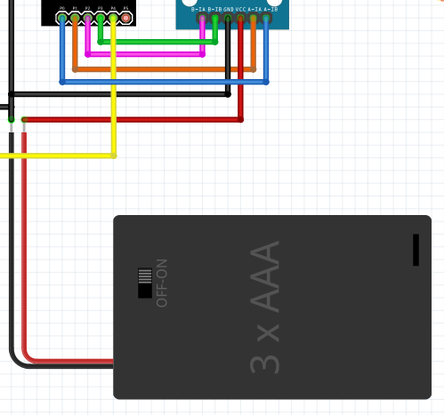
Shared Power Source
All of our components get their power from a single source, the AAA batteries. So how can we share it across three components? Well our breadboard can be used to do this.

In this simplified diagram we see the power enter the breadboard from the AAA battery pack. This is then split off with a GND and Vcc connection to every component used in the build, giving them the power they need to do their job.
Final Thoughts
Who would of thought this tiny little board would bring such joy and stress :)
This was a fun and at times a rather stressful project. But what got me through it were the tweets of encouragement and help that I received from the community. My top tips when facing problems in a project.
Step away from the problem for a short time, get a coffee, go for a walk etc. Return fresh to the problem.
Google, someone has bound to have had a similar problem.
Ask someone for help.
Use each failure as an opportunity to learn. Failure is a great teacher, do not be disheartened!
Happy Hacking!
Update 21/09/2019 A fix for the motor boot issue.
Thanks to some super advice from Heeed we have a fix for an issue.
Spinning motor on boot
By default one of the robot's motors will spin when the robot is powered up. This is due to the pin on ATtiny85 being pulled high on boot. If the pin on the ATtiny85 is swapped with the pin used for the sensor, then all is good. Just remember to alter the code accordingly.