Friday Fun: Cardboard Circuit
As a kid cardboard was my gateway to making, but why?
Cardboard is cheap, plentiful and I can hack it with simple tools (scissors, glue, felt pens etc) It can also be anything that I want it to be.
True story: My best friend, Scott and I made my bedroom door into the doorway to the TARDIS using cardboard, tape and felt pens.
So what are we making this time?
We shall be making a simple circuit using some very cheap components, no microcontroller or computer required!
For this project you will need
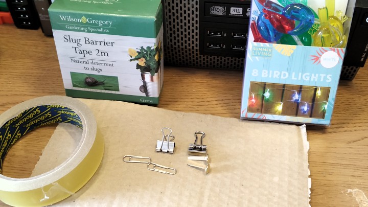
- A pack of LED lights from Poundland
- 2 x AA batteries
- Copper slug tape
- 1 x Brass split pin
- 4 x bulldog clips (these must be bare metal, not plastic covered)
- Cardboard
- Felt pens
- Scissors
- Wire Strippers
- Multimeter (optional but helps)
Building the circuit
Drawing the circuit
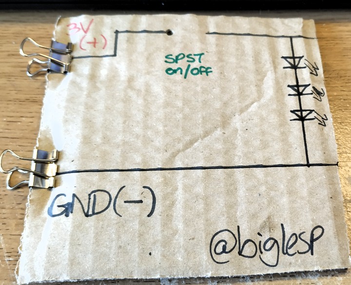
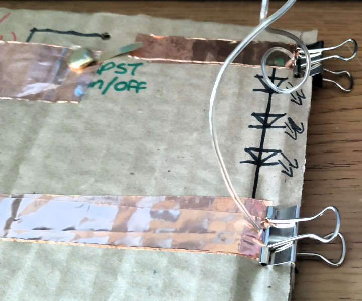
On a piece of card I drew the circuit for this project, at the top of the circuit is where 3V will be connected, leading to a Single Pole Single Throw (SPST) switch which will close a circuit when a user presses it. This enables the current to flow to the LED parrots (Light Emitting Diode). But in order for the circuit to work the parrots need to also be connected to Ground (GND) and so the bottom part of the circuit connects the GND of the battery pack, to the GND of the parrots.
Adding the tracks
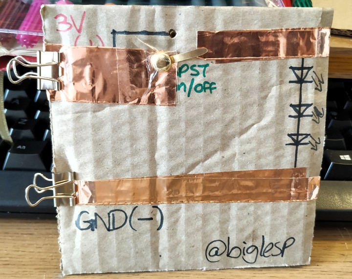
If you look at a circuit board then you will see "tracks" of copper that are the pathways where data / power flow.
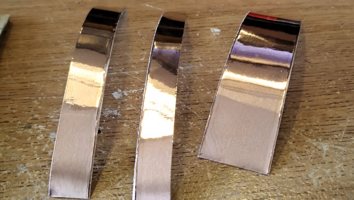
Copper is a great conductor and so we shall use it to make a circuit on the cardboard. Copper slug tape (£1 for 2 metres) is cheap and very useful for this project. We shall use it to make the tracks of the circuit.
Please note
Copper slug tape is only conductive on the copper side. The glue is an insulator.
Add a switch

The brass split pin will serve as a momentary switch. This is a switch that will remain open and requires the user to press it down to close the circuit. To make this we need to split the longest leg of the pin out so that it is stretched out as far as possible. Ensure that the long leg can reach the right side of the switch circuit!
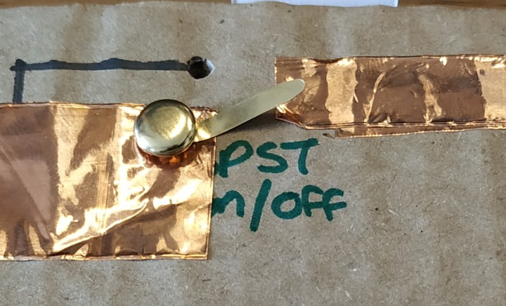
Now make a hole through the cardboard using a pen or screwdriver. Slide the short leg through the hole and then fold it back on the reverse of the cardboard. This will hold it in place, but I also used a little cellotape (sticky backed plastic / adhesive tape) to hold the button in place.
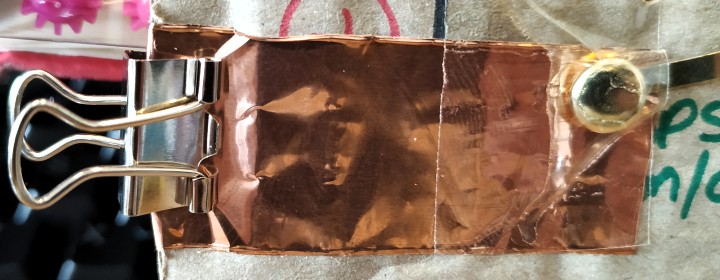
Once the switch is in place, connect the bulldog clips to the four corners. (3V and GND on the left and to the LED connections on the top right and bottom right.)
I've got the power and parrots!
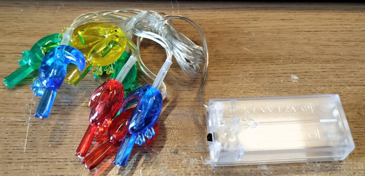
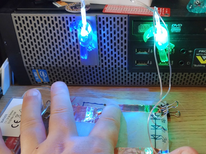
The LEDs for this project are some rather fetching parrots that contain white LEDs. The colour of the parrots plastic shell is highlighted when the power is turned on.
We need the battery box and the parrots to be separated.
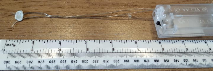
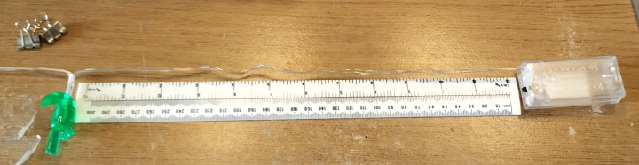
So using some wire cutters, scissors (not your best scissors!) snip the battery box so that there is 15cm (6in) of wire from the battery to the snip.
Using your wire strippers, strip the 1cm of wire from the two wires coming from the battery box.
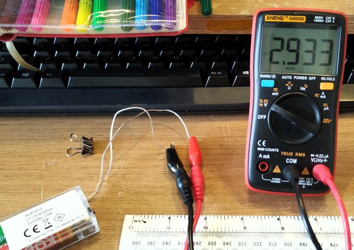
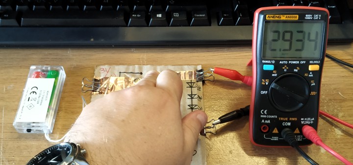
To test the battery box and the polarity of the wires. Insert 2x AA batteries into the battery box, but do not turn it on yet and then connect the wires to a multimeter. Set your multimeter to read DC voltage, and then turn on the power.
If you are lucky then you may get the polarity correct first time, and the value on the multimeter will show something like DC 3.00v, in my case I got DC 2.933v. This means the polarity is correct. But if you see a negative number, DC-3.00v for example, then the wires are in the wrong polarity. Swap them round and test again.
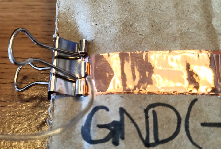
Once we know the polarity we can remove the wires one by one from the multimeter and connect them to the 3V and GND bulldog clips. By using the clips to grip the wires to the copper tape we get a decent electrical connection.
Optional Step - Test the circuit before attaching LEDs
This is totally optional, I performed this test as the multimeter was already on my desk and ready to use. I connected the COM clip of my multimeter to GND of the circuit, and the V clip to the top right LED connection, which will receive 3V when the circuit is closed.
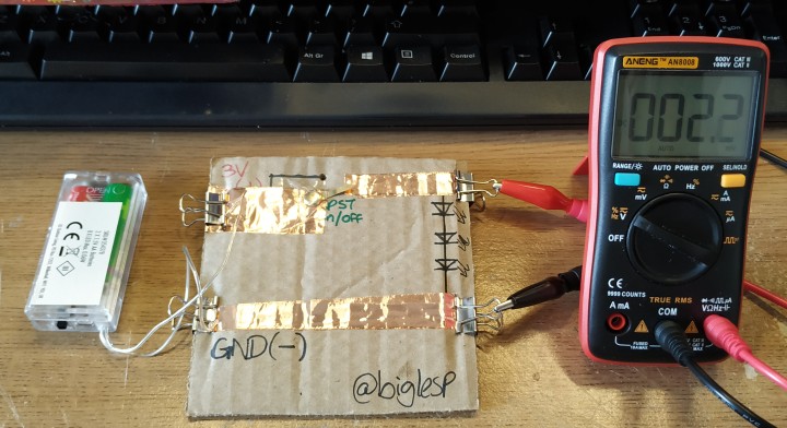
Here is the circuit test when it is open circuit, the button has not been pressed
Here is the circuit test when it is closed circuit, the button has been pressed, note that we can see the voltage change on the multimeter
Parrots!

The LED parrots are the final step in this project, so take the chain of eight parrots that you already have, strip the wires where they were cut from the battery box. Now we need to cut two parrots from the chain of eight. So count two parrots, and snip the wires after the second parrot.
With the parrots freed and their wires stripped, connect them to the top right and bottom right of the circuit.
PRESS THE BUTTON!!
Ok turn on the power at the battery box, then press the brass pin button we created.
Do the parrots light up?
If not then swap their wires around on the circuit board and try again.
You made it!
You have done it! You have made a circuit using cardboard, office equipment and some battery powered parrots from Poundland. No computers or brains, just simple electronics and logic!