Friday Fun: Making an LED blink...with a Commodore 64
Yes, you read that correctly! Blinking an LED with a C64 and BASIC.
In a previous post you have seen me messing around with a Z80 board via BASIC, well this cemented a long held yearning to learn BASIC and I wanted to learn it via a machine that was a big part of my life, the Commodore 64. So using my Christmas money I bought a C64 to play with.
Before I get too far into this post, I would like to thank Sven Petersen for his advice and knowledge when writing this blog post!
BASIC but a little more advanced...
I wanted to fulfill two goals.
- Create a simple project in BASIC that is more interesting than just a loop of text.
- Make an LED blink using BASIC.
This made me very happy!
— biglesp (@biglesp) February 7, 2020
The Hello World of electronics is flashing an LED... So here I am doing that on a Commodore 64! With thanks to @TheProjectGeek breakout board! pic.twitter.com/zQi1agtYiU
So I combined both wishes into one simple project, but I needed something to help connect the real world to the Commodore 64.
If you like what you read...
Sorry to interrupt! But would you like to buy me a cup of coffee? It helps me to pay for hosting this blog, and to buy stuff to hack from Poundshops / Dollar Stores which are used in free projects on this blog. Thanks!

C64 userport breakout board
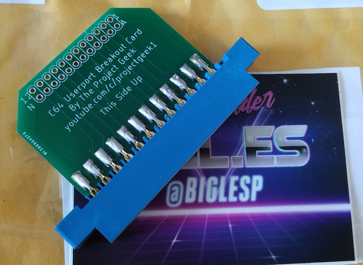
The Commodore 64 has a rear user port, and this can be used to connect electronic components to the C64. You can make your own connector board, but I saw The Project Geek's C64 Userport Breakout Card on sale at Tindie...well it made sense to grab one!
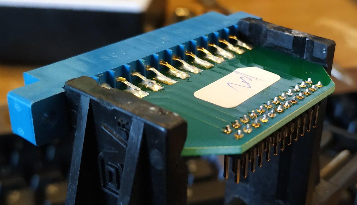
When it arrived, all I needed to do was a little soldering, you can buy them pre-soldered, but I love soldering!
C64 Userport pinout
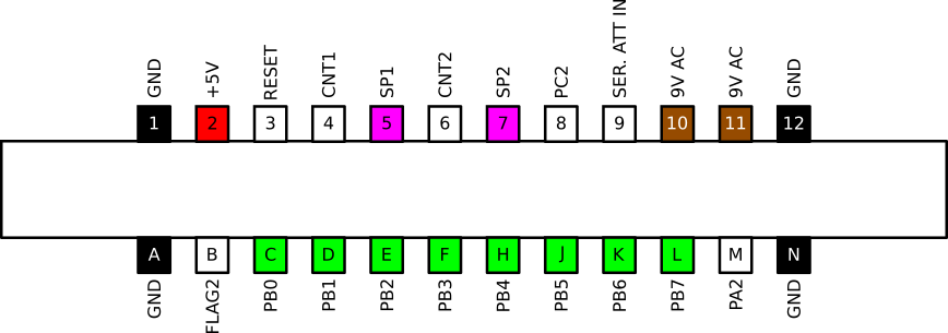
Note that this pinout is as we look at the userport from the back
| Pin | Name | Direction | Info |
|---|---|---|---|
| 1 | GND | - | Ground (0V) |
| 2 | +5V DC | - | Max 100mA |
| 3 | RESET | in/out | Pull LOW to reset |
| 4 | CNT1 | PROG | Count 1, Connected to CNT of CIA #1 |
| 5 | SP1 | PROG | Serial Port 1 |
| 6 | CNT2 | PROG | Count 2, Connected to CNT of CIA #2 |
| 7 | SP2 | PROG | Serial Port 2 |
| 8 | PC2 | OUT | Port Control 2 |
| 9 | SER ATT IN | OUT | Serial Attention |
| 10 | 9V AC | - | 9V Supply voltage, take care! |
| 11 | 9V AC | - | 9V Supply voltage, take care! |
| 12 | GND | - | Ground (0V) |
| A | GND | - | Ground (0V) |
| B | FLAG2 | IN | A negative edge at this pin sets the FLAG bit in the interrupt control register of CIA #2 |
| C - L | PB0-PB7 | PROG | Port Register B of CIA #2 Each pin can be programmed as an input or output |
| M | PA2 | PROG | Port Register A, bit 2 of CIA #2 |
| N | GND | - | Ground (0V) |
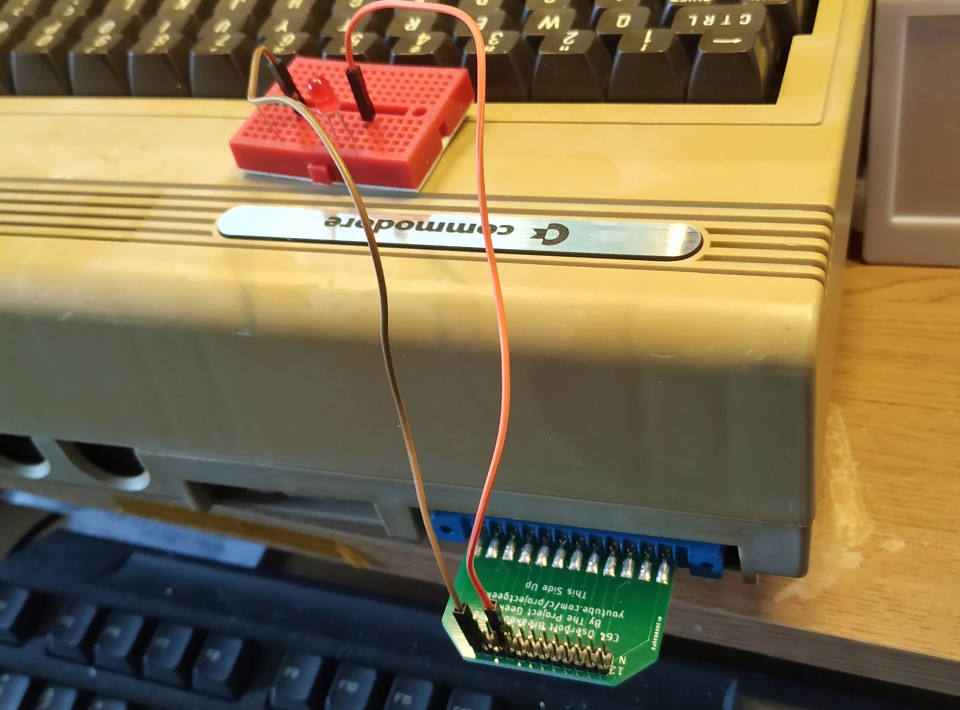
I then plugged the breakout board into the rear of the C64.
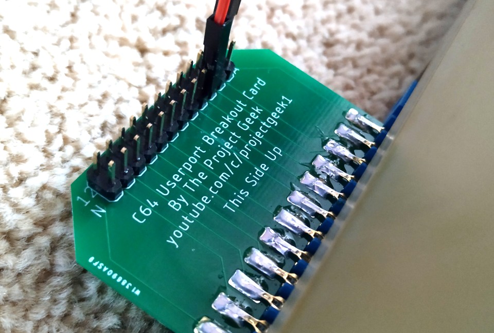
Making sure that the breakout board was the right way up.
Can we make an LED flash now?
Ok!!!
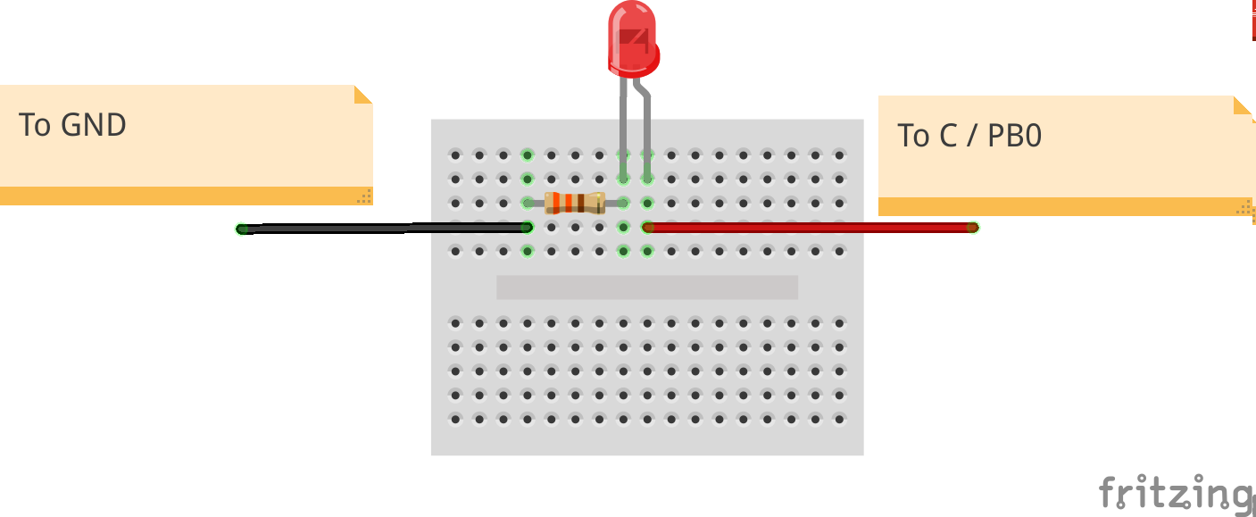
For this I created a simple circuit on a breadboard using a red LED, and a 330 Ohm resistor (Orange, Orange, Brown, Gold) which saw me connect the long leg of the resistor to userport pin C (PB0) and the short leg to GND via the resistor. These were connected using the C64 breakout board, which was then connected to the C64 userport.
Writing the code
Powering up the C64 and we immediately see the C64 BASIC screen and from here we are going to write a short project to control the LED.
First I set all of the PB pins to be outputs by using a POKE to change a value store in a memory address. Using 255 sets the pins to outputs, each with 5V available. Take care as a short circuit can be deadly for the C64. If I ever need to set the pins as inputs I can use POKE56579,0.
To set PB0 pin as an output.
POKE56579,1
To print that I am setting the pin "on", handy for debug.
10 PRINT "ON"
To turn PB0 on, so that the LED lights up.
20 POKE56577,1
Then I turn off the LED, with a quick print for debug.
30 PRINT "OFF"
40 POKE56577,0
The last line is to tell the code to loop back to ine 10 and repeat the process.
50 GOTO 10
With the code typed in, I finally typed RUN and watched the LED flicker to life.
Need to stop the code? Press
RUN STOPon the left of the keyboard, just above the Commodore key. Want to run the code again? Don't type RUN, just pressSHIFT+RUN STOPand it will start!
But wait Les, you didn't set a delay between the LED turning on and off?!
Correct I didn't mention a delay! I'm still looking into the correct way to add a delay, but thankfully we can see the flicker of the LEDs thanks to the C64 being a little slower than a Raspberry Pi ;)
But if you really want to add a delay, then using a for loop is a quick and easy method.
Here is the complete code including a one second delay between the LED blinking.
POKE56579,1
10 PRINT "LED ON"
20 POKE56577,1
30 FOR I=1TO1000:NEXT
40 PRINT "LED OFF"
50 POKE6577,0
60 FOR I=1TO1000:NEXT
70 GOTO 10
So there we have it!
A Commodore 64 controlling an LED, the first step in my plan to write a useful physical computing project with the Commodore 64 and BASIC.