Friday Fun - Neopixel Cinema Sign
This is another project for myself, not because I am vain but rather because I like blinky lights!
Neopixels, is that Keaunu Reeves in The Matrix?
WS2811, WS2112B and SK6812 RGB LEDs are better known as Neopixels, which is a brand name from Adafruit. But they all share common features in that every LED in a chain can be individually controlled (addressable) and we can alter the colour of each LED, brightness and speed at which they turn on and off. Suffice to say I love neopixels.
So in this project we are going to build a small cinema sign with embedded NeoPixel LEDs.
For this project you will need

- A cinema sign, these can be found in the UK: Poundland (not a £1), The Works, Argos, Asda.
- An ATtiny85
- Strip of NeoPixels
- Micro USB cable
- Soldering equipment
- Lengths of wire, 3 colours preferably
- Double sided tape / hot glue
Setting up the ATtiny85
First install the Arduino IDE
You will need to install the Arduino IDE in order to complete this project.
Add the ATtiny85 Board

The code for the ATTiny85 is written using the Arduino IDE, so open the application and before we write any code we need to ensure that we have our Attiny85 listed as a usable board.
To do this click on File >> Preferences and in the new dialog box look for the Additional Board Manager URLs and look for the overlapping windows icon to the right. Click on this and paste the following URL into the new window. Then press Ok.
http://digistump.com/package_digistump_index.json

So now we can add the ATTiny85 to our list of boards. Go to Tools >> Board >> Boards Manager and wait for a few seconds until the list of boards has been updated. Once you have control, in the top right of the screen use the search box and search for digispark and then install the board. The final step before we start coding is to tell Arduino what board we are using, so go back to Tools >> Board and select Digispark (Default - 16.5mhz).
Install the NeoPixel Library
![]()
We next need to install the Adafruit NeoPixel library. So click on Sketch >> Include Libraries >> Manage Libraries and in the new dialog box, there will be a search box in the top right, enter the word neopixel in there and it will search for that word.
Once you see the Adafruit NeoPixel by Adafruit entry click on it and then Install. This will install the library and the example sketches for the Adafruit NeoPixel library!
The Code
For this project we are going to reuse the NeoPixel strandtest project from the Adafrut_NeoPixel examples. But we are going to modify the code to match our project.
We are using 20 NeoPixel LEDs, connected to Pin 1 of the Attiny85 so we start the code by editing the line
#define PIN 6
To read
#define PIN 1
Next look for the following line
Adafruit_NeoPixel strip = Adafruit_NeoPixel(60, PIN, NEO_GRB + NEO_KHZ800);
Change it to read
Adafruit_NeoPixel strip = Adafruit_NeoPixel(20, PIN, NEO_GRB + NEO_KHZ800);
The next line to look for is
colorWipe(strip.Color(255, 0, 0), 50); // Red
Change this to read
/*colorWipe(strip.Color(255, 0, 0), 50); // Red
But what does
/*mean?
In the Arduino language this is the start of a multi line comment. This can be used to write a paragraph of comments to aid the user. So if we start with/*then we must end with*/
We now need to end the multi line comment which will turn off a number of examples in the Adafruit strandtest code. All we need is the rainbowCycle(20) demo, and we shall do that by changing
rainbow(20);
to
rainbow(20);*/
The final change to make is to comment out a single line which will
theaterChaseRainbow(50);
to
//theaterChaseRainbow(50);
So now all of the code should look like this.
#include <Adafruit_NeoPixel.h>

#define PIN 1

// Parameter 1 = number of pixels in strip
// Parameter 2 = Arduino pin number (most are valid)
// Parameter 3 = pixel type flags, add together as needed:
//   NEO_KHZ800  800 KHz bitstream (most NeoPixel products w/WS2812 LEDs)
//   NEO_KHZ400  400 KHz (classic 'v1' (not v2) FLORA pixels, WS2811 drivers)
//   NEO_GRB     Pixels are wired for GRB bitstream (most NeoPixel products)
//   NEO_RGB     Pixels are wired for RGB bitstream (v1 FLORA pixels, not v2)
Adafruit_NeoPixel strip = Adafruit_NeoPixel(20, PIN, NEO_GRB + NEO_KHZ800);

// IMPORTANT: To reduce NeoPixel burnout risk, add 1000 uF capacitor across
// pixel power leads, add 300 - 500 Ohm resistor on first pixel's data input
// and minimize distance between Arduino and first pixel.  Avoid connecting
// on a live circuit...if you must, connect GND first.

void setup() {
  strip.begin();
  strip.show(); // Initialize all pixels to 'off'
}

void loop() {
  // Some example procedures showing how to display to the pixels:
  /*colorWipe(strip.Color(255, 0, 0), 50); // Red
  colorWipe(strip.Color(0, 255, 0), 50); // Green
  colorWipe(strip.Color(0, 0, 255), 50); // Blue
  // Send a theater pixel chase in...
  theaterChase(strip.Color(127, 127, 127), 50); // White
  theaterChase(strip.Color(127,   0,   0), 50); // Red
  theaterChase(strip.Color(  0,   0, 127), 50); // Blue

  rainbow(20);*/
  rainbowCycle(20);
  //theaterChaseRainbow(50);
}

// Fill the dots one after the other with a color
void colorWipe(uint32_t c, uint8_t wait) {
  for(uint16_t i=0; i<strip.numPixels(); i++) {
      strip.setPixelColor(i, c);
      strip.show();
      delay(wait);
  }
}

void rainbow(uint8_t wait) {
  uint16_t i, j;

  for(j=0; j<256; j++) {
    for(i=0; i<strip.numPixels(); i++) {
      strip.setPixelColor(i, Wheel((i+j) & 255));
    }
    strip.show();
    delay(wait);
  }
}

// Slightly different, this makes the rainbow equally distributed throughout
void rainbowCycle(uint8_t wait) {
  uint16_t i, j;

  for(j=0; j<256*5; j++) { // 5 cycles of all colors on wheel
    for(i=0; i< strip.numPixels(); i++) {
      strip.setPixelColor(i, Wheel(((i * 256 / strip.numPixels()) + j) & 255));
    }
    strip.show();
    delay(wait);
  }
}

//Theatre-style crawling lights.
void theaterChase(uint32_t c, uint8_t wait) {
  for (int j=0; j<10; j++) {  //do 10 cycles of chasing
    for (int q=0; q < 3; q++) {
      for (int i=0; i < strip.numPixels(); i=i+3) {
        strip.setPixelColor(i+q, c);    //turn every third pixel on
      }
      strip.show();

      delay(wait);

      for (int i=0; i < strip.numPixels(); i=i+3) {
        strip.setPixelColor(i+q, 0);        //turn every third pixel off
      }
    }
  }
}

//Theatre-style crawling lights with rainbow effect
void theaterChaseRainbow(uint8_t wait) {
  for (int j=0; j < 256; j++) {     // cycle all 256 colors in the wheel
    for (int q=0; q < 3; q++) {
        for (int i=0; i < strip.numPixels(); i=i+3) {
          strip.setPixelColor(i+q, Wheel( (i+j) % 255));    //turn every third pixel on
        }
        strip.show();

        delay(wait);

        for (int i=0; i < strip.numPixels(); i=i+3) {
          strip.setPixelColor(i+q, 0);        //turn every third pixel off
        }
    }
  }
}

// Input a value 0 to 255 to get a color value.
// The colours are a transition r - g - b - back to r.
uint32_t Wheel(byte WheelPos) {
  WheelPos = 255 - WheelPos;
  if(WheelPos < 85) {
   return strip.Color(255 - WheelPos * 3, 0, WheelPos * 3);
  } else if(WheelPos < 170) {
    WheelPos -= 85;
   return strip.Color(0, WheelPos * 3, 255 - WheelPos * 3);
  } else {
   WheelPos -= 170;
   return strip.Color(WheelPos * 3, 255 - WheelPos * 3, 0);
  }
}
Flash the code!
To flash the code to our ATtiny85 we first need to make sure that we have selected the correct board from Tools >> Board which is Digispark (Default - 16.5mhz) and then click on upload (the arrow pointing to the right under the Edit menu.)
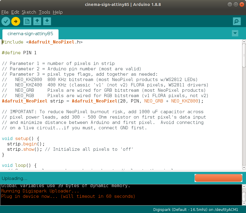
In the console output it will instruct you to insert the USB lead attached to your ATtiny85. You have 60 seconds to do so, take your time don't rush! Once the code has been flashed you can unplug the Attiny85, and now we can start building the lights!
The NeoPixels
Carefully open the case using a flat blade screw driver, start at the short sides of the case as the plastic is slightly stronger here. With the front off remove the exisiting LED light from the cinema box, put it in your bits box for another project. Also remove the power switch as the hole it leaves is handy for our USB cable to go into.
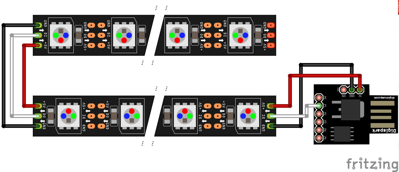
Keep an eye on the direction of the arrows, they show the direction in which data will travel!
The wiring for this project is really straightforward.
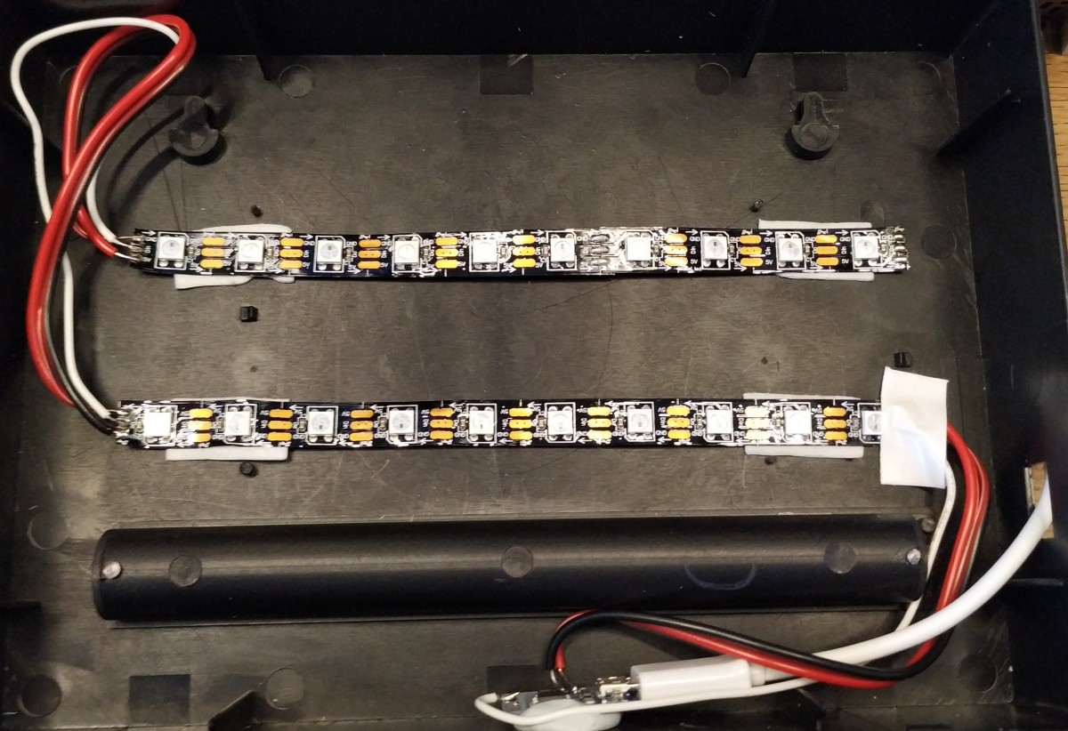
We need to cut 2 x 10 LED lengths of NeoPixels.
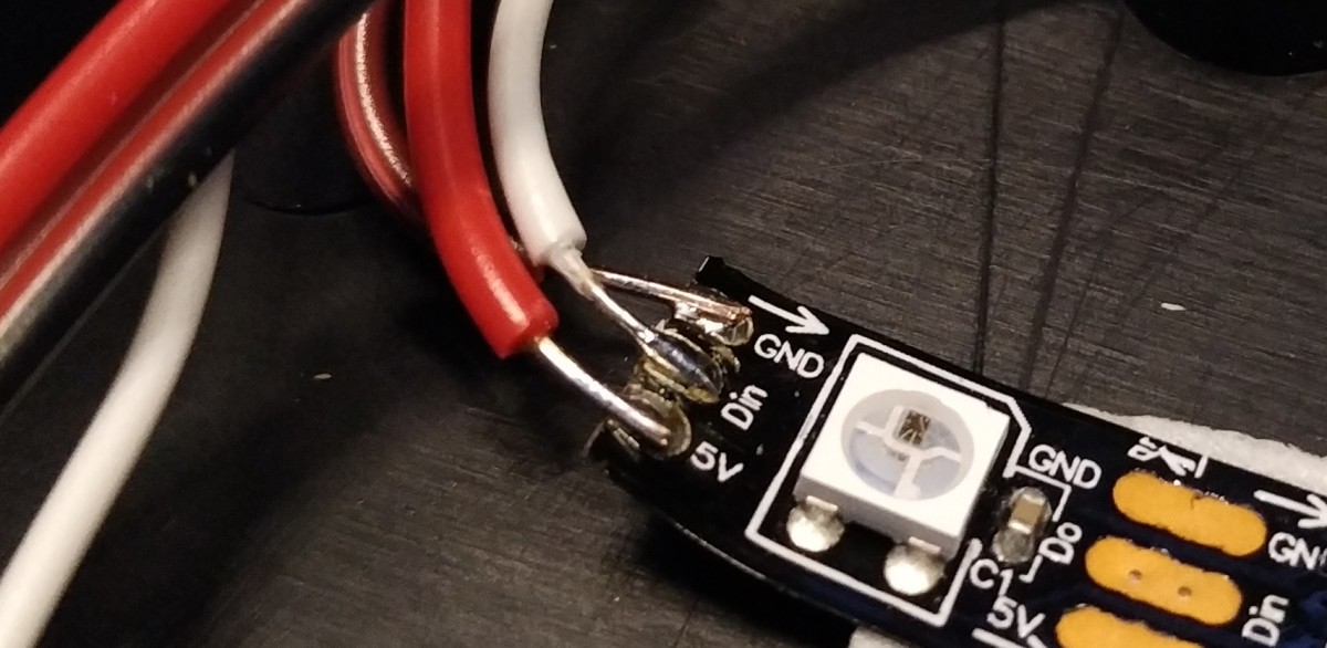
Now with your soldering iron, use a little solder to "tin" each connection (the gold pads.)
On the NeoPixel strips we need to tin
5V - Otherwise known as VCC
Din - Data In
DO - Also known as DOUT, Data Out
GND - Connection to a GND pin
On the ATtiny85 connect wires from
5V - Otherwise known as VCC
P1 - Data Out
GND - Connection to a GND pin
The path we take to connect the first NeoPixel strip is..
P1 to DIN on the NeoPixel
5V to 5V
GND to GND
Then to connect the first strip to the second we solder wire from
DO to DIN (this enables the data to reach the LEDs in the second strip.
5V to 5V
GND to GND
Now stick the strips down inside the case. I used some double sided foam tape but you can use hot glue, super glue etc. To hold the ATtiny85 in place I used some modeling clay / blu tack.
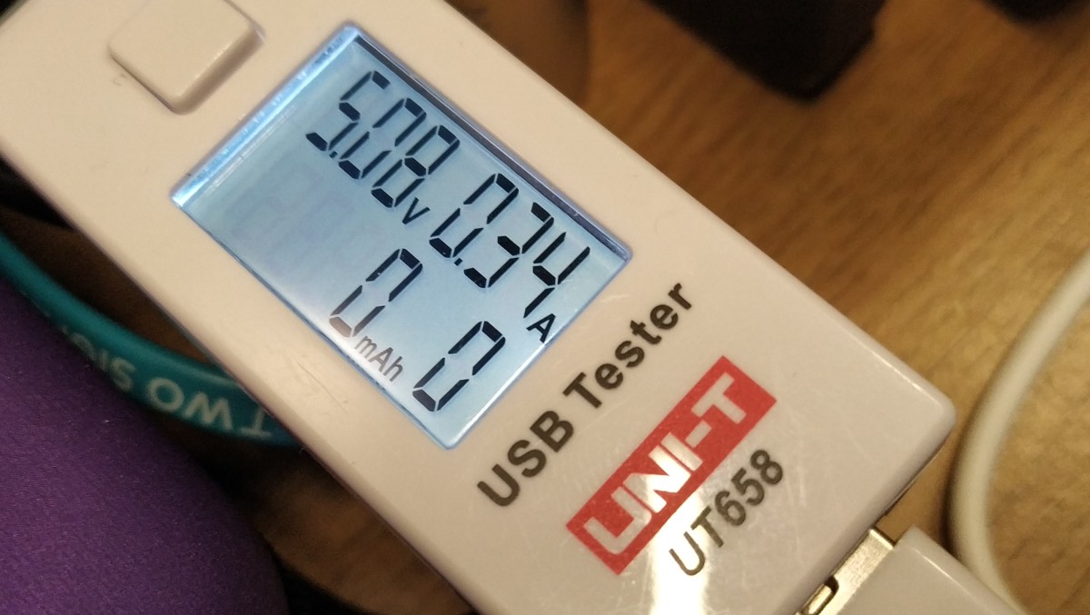
In use the cinema sign on draws 340mA of current
Lastly insert your micro USB lead and then attach it to a 5V power source (USB power supply / battery / USB port) and wait for the LEDs to light up!

If all goes well your sign will illuminate! So now you can close it up and find a nice place to show off your creation!
Extra Information for Ubuntu
I noticed on two Ubuntu machines (fresh install of 18.04) that I could not flash any code to the ATtiny85 despite having the correct board in the Arduino IDE. Turns out that I had a permissions issue and that left me unable to write to the ATtiny85.
The error was similar to micronucleus connect: Assertion `res >+4` failed and the solution was...
Open a terminal and type
$ sudo nano /etc/udev/rules.d/49-micronucleus.rules
In the new file paste the following
# UDEV Rules for Micronucleus boards including the Digispark.
# This file must be placed at:
#
# /etc/udev/rules.d/49-micronucleus.rules    (preferred location)
#   or
# /lib/udev/rules.d/49-micronucleus.rules    (req'd on some broken systems)
#
# After this file is copied, physically unplug and reconnect the board.
#
SUBSYSTEMS=="usb", ATTRS{idVendor}=="16d0", ATTRS{idProduct}=="0753", MODE:="0666"
KERNEL=="ttyACM*", ATTRS{idVendor}=="16d0", ATTRS{idProduct}=="0753", MODE:="0666", ENV{ID_MM_DEVICE_IGNORE}="1"
#
# If you share your linux system with other users, or just don't like the
# idea of write permission for everybody, you can replace MODE:="0666" with
# OWNER:="yourusername" to create the device owned by you, or with
# GROUP:="somegroupname" and manage access using standard unix groups.
Then press CTRL + O ENTER CTRL + X to save and exit.
Lastly reload the udev rules to ensure the permissions are updated.
$ sudo udevadm control --reload-rules
Then retry :)
Source of the information https://digistump.com/wiki/digispark/tutorials/linuxtroubleshooting