Raspberry Pi: Breadboard Pi Bridge
tl;dr Alex is running a crowdfunder for his latest project. So go and back it!
What is the first hurdle when using the Raspberry Pis GPIO?
GPIO?
General Purpose Input Output, the 26/40 pins on a Raspberry Pi that enable us to send and receive signals to components using programming languages such as Python and Scratch.
Pin numbering!
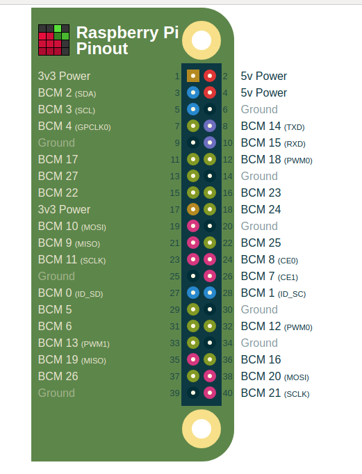
Image taken from https://pinout.xyz an essential reference for Raspberry Pi makers and hackers! Go and use it!
The Raspberry Pi has a few pin numbering schemes but the two most common are
- Physical, where the pins are numbered in a logical manner, starting with 1 at the top left of the board being the nearest pin to the micro SD card slot.
- Broadcom (BCM), this refers to how the pins are connected to the brains of the Pi. The numbering is not logical to a human, but it is relevant to the Pi.
The de facto standard supported by the Raspberry Pi Foundation is Broadcom, and that means we need to learn the pin out (location of pins) of the GPIO.
Helping Hand
Alex Eames is a serial crowdfunder and he has successfully undertaken many kickstarted products. I should know as I have backed many of them! From PCB rulers that show us the GPIO pinout, to elaborate light shows using easy to fit components, Alex has done them all!
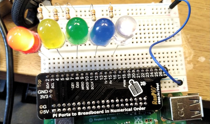
For his latest project Alex has created a custom add on board for all 40pin models of Pi (A+, B+, 2, 3, 3B+, Zero W) that connects to the GPIO and then breaks out all 40 pins into a breadboard friendly package. 3V and GND connections are made directly into the rails of your breadboard, with the option to also solder your own 5V connection.
Remember: The Raspberry Pi does not like 5V on its GPIO pins, it can damage your pins and / or board so be careful
With Breadboard Pi Bridge we can build projects directly on a breadboard with less wires, which will reduce the amount of time we spend debugging wiring errors.
It also comes with a laser cut board holder that will keep you Pi and breadboard close together. The optional cover is handy and provides a breakaway cut out for the 3A+/3B+ PoE header.
Early Access
Looks familiar! pic.twitter.com/xA4xWoqYKq
— biglesp (@biglesp) March 26, 2019
Alex sent me a board to play with, and using the included LEDs and a little GPIO Zero Python code, I managed to make a nice fading light project.
from gpiozero import PWMLED
from time import sleep
red = PWMLED(2)
yellow = PWMLED(5)
green = PWMLED(8)
blue = PWMLED(12)
white = PWMLED(16)

LEDS = (red, yellow, green, blue, white)
brightness = (0,0.1,0.2,0.3,0.4,0.5,0.6,0.7,0.8,0.9,1.0)
while True:
    for colour in LEDS:
        for level in brightness:
            colour.value = level
            sleep(0.01)
    for colour in reversed(LEDS):
        for level in reversed(brightness):
            colour.value = level
            sleep(0.01)
So go and back it!
The board is available for £12 via Alex's own website and comes with everything you need to build the laser cut frame and components to make blinky LEDs!