micro:bit - Hacking the GPIO - Updated!
So yesterday on the train...I saw this tweet.
Just had GREAT yr4 after school club using #bbcmicrobit 😀 BUT trying2do traffic lights & struggled w/ short circuits pic.twitter.com/xsp1upJs3q
— Ben Smith (@ManchesterBudo) 23 February 2016
It got me and a few other geeks thinking of ways to hack a "better" interface. Yes the term "better" is subjective but lets see what we can do.
So this morning I dug out my Meccano kit, salvaged from charity shops. This was prompted thanks to a tweet from Michael Sparks.
@ManchesterBudo More seriously we've used nuts and bolts to attach wires. Meccano size ones work. @PrimarySi @biglesp @davidames
— Michael (@sparks_rd) February 24, 2016
But the screws that come with a Meccano kit slightly overlapped the slim GPIO pins that are either side of the main GPIO. I didn't want to risk a short so I did a little Googling, Tweeting and searching on the Screwfix website.
Thanks to Jo Claessens for a top tip!
@biglesp Loving this. Also found that using bolts with a countersunk head give enough clearance across the small pins. great blog!
— Jo Claessens (@mrsclaessens) February 26, 2016
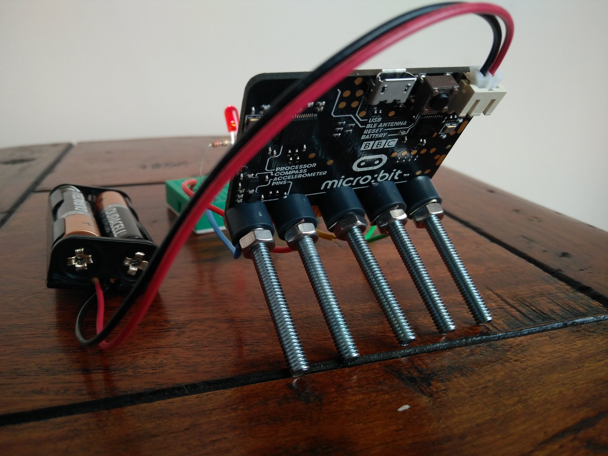
So with a little thought and a lot of hacking I made this.
I used
- 5 x M4 Countersunk machine screws. I could only get 40mm long screws, but 15mm is ideal length.
- 5 x M4 Nuts
- 5 x Meccano plastic spacers
- Wire cut to length
- Breadboard
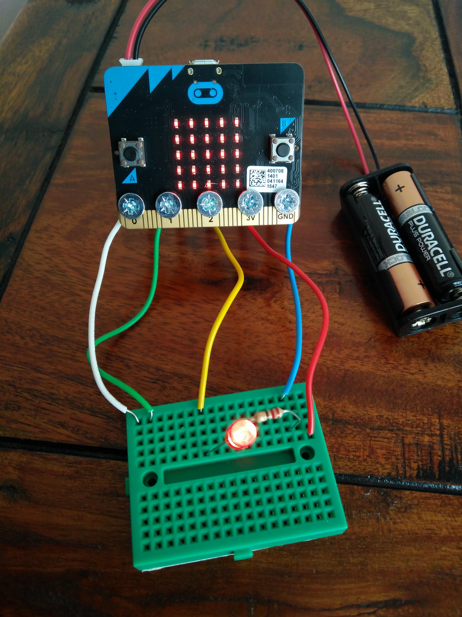
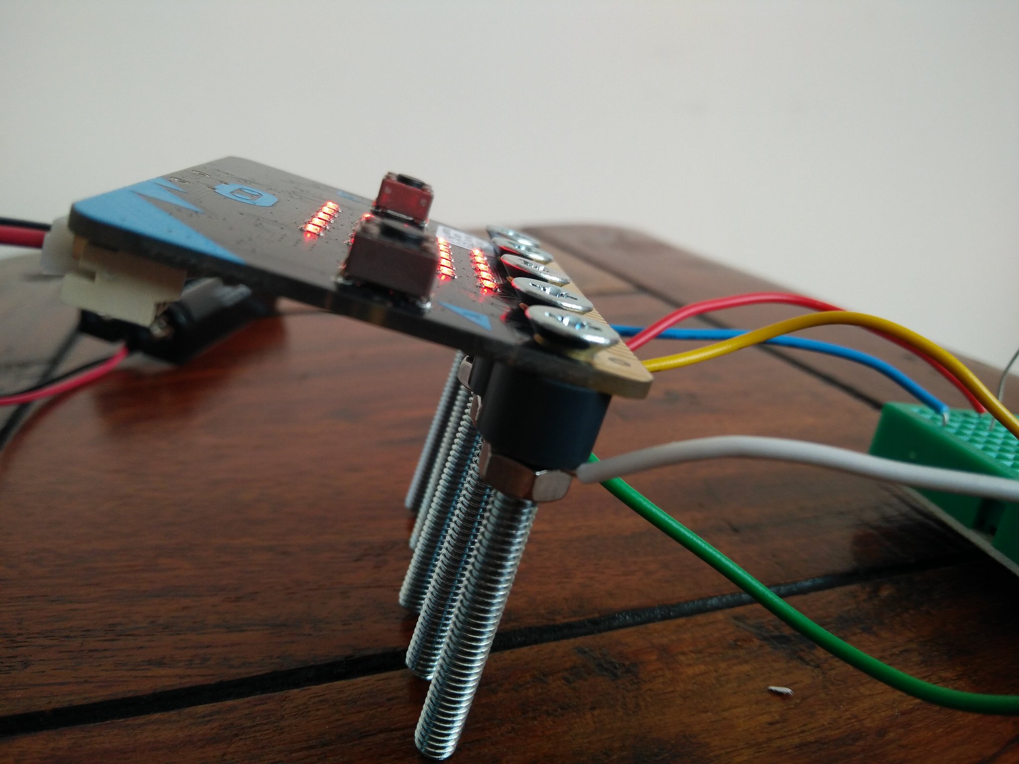
Using a countersunk machine screw is important as it means that no part of the screwhead touches any other GPIO pin. We need to reduce the chances of a short as this can lead to damage of the micro:bit and more importantly possible injury.
I wrapped the wires around the screw for each GPIO pin. They are caught between the plastic spacer and the nut to provide a tight connection.
So after the hardware was installed I created a simple circuit on a breadboard using an LED connected to pin 2, a 220 Ohm resistor (RED-RED-BROWN-GOLD) connected to the cathode (short leg) of the LED and in line to the Ground pin.
And it works, I tested each output (0,1,2 and 3V) with the Mu Python editor and each test involved lighting all of the LED on the matrix and powering an LED on each of the available pins. I'm happy to say that it was a success.
I'm in the process of securing more machine screw samples along with nylon nuts and washers to make this into a possible kit.