Friday Fun: Light up a life!
Right now the world is in lock down, not something that I thought I would ever write. We need to show the world that in this time of darkness, there is still some light!
Who needs the light?
Everyone! In a time of darkness there are those that give their time, and their lives to protect others. The "key workers" are those that provide us with medical care, that look after our older relatives, they stock our supermarkets with food, they deliver the food, they make the things that we need.
The Rainbow
In the UK children are creating rainbows in their windows. These rainbows are their to light up the lives of key workers. Reminding them that they are special and that we give thanks to them, and it reminds us that we need to stay inside and keep everyone safe.
So what shall we build for them?
We are going to build a rainbow, using arts and crafts materials, and then add a little electronics to create a light show.
This project is deliberately simple to encourage children and young adults to have a go and learn how to wire up some basic electronics.
Building the project
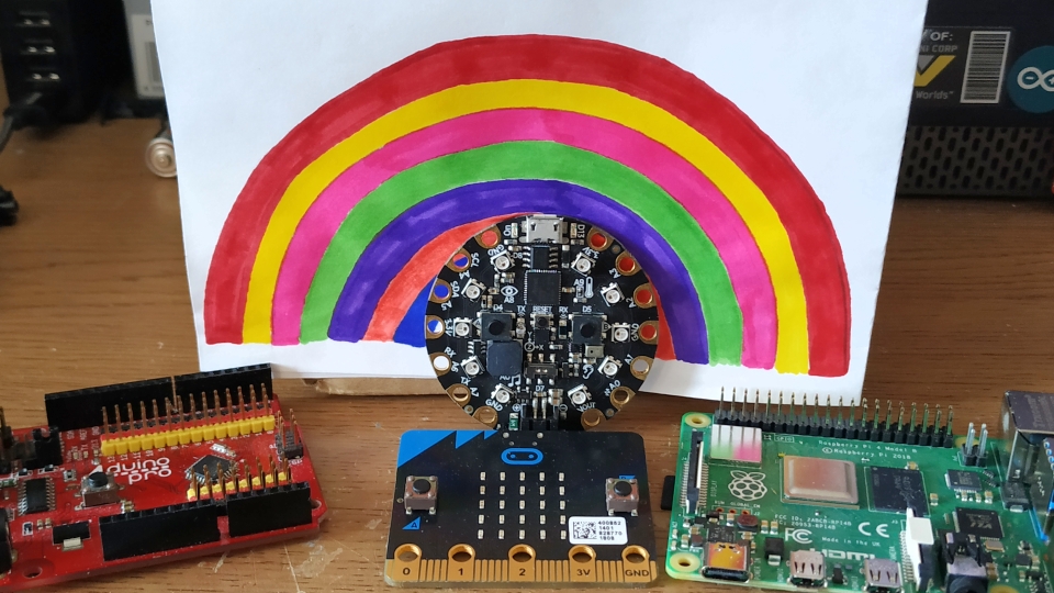
To enable any young maker to attempt this project I have written the project using four different boards.
The Arduino, micro:bit, Adafruit's Circuit Playground Express (CircuitPython) and Raspberry Pi are the target boards.
What do I need to build the project?
- 3 x LEDs, these can be any colour that you have to hand. I chose red, green and blue.
- 3 x 220 Ohm resistors (RED-RED-BROWN-GOLD)
- Arts and crafts materials to make the rainbow
- Masking tape (Electrical tape, or sticky backed plastic (cellotape) will also work)
- For the Raspberry Pi
- 9 x Male to Male jumper wires
- For the micro:bit or CircuitPython
- 6 x Crocodile clips
- 3 x Female to Male jumper wires
- 3 x Female to Female jumper wires
- For the Arduino
- 3 x Female to Male jumper wires
- 3 x Female to Female jumper wires
All of the code examples and images
You can download all of the code, images and diagrams for offline use.

Hi reader!
First make a rainbow
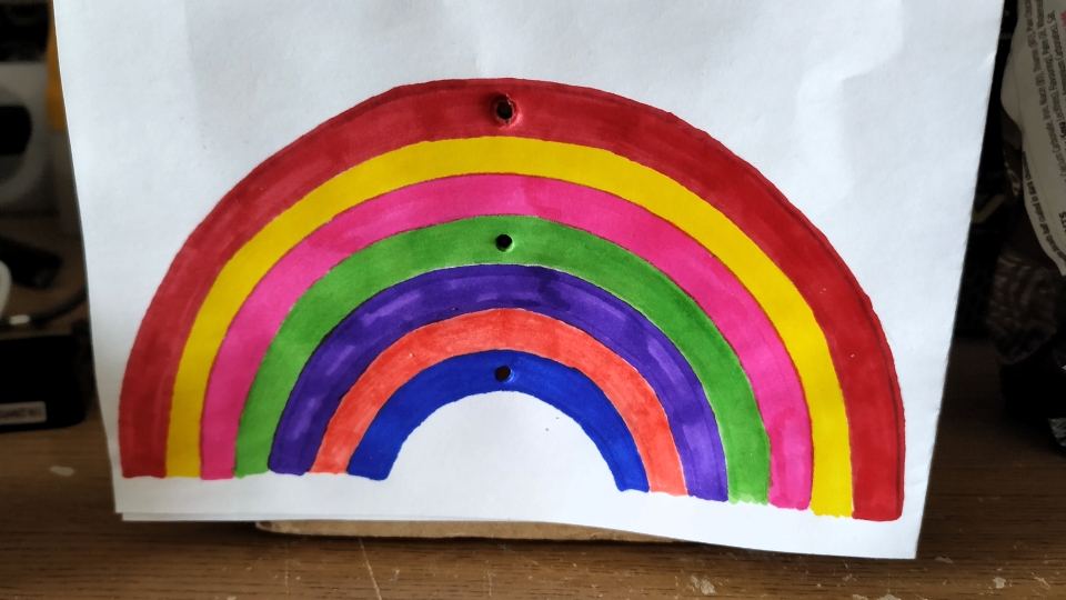
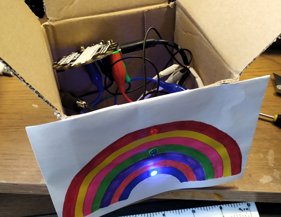
Get out your crayons, paint, pens and draw a rainbow. Make it however you wish, there is no wrong way to do it! Be creative and have plenty of colour. I asked MrsP to make me a rainbow and she spent a happy hour making a small rainbow on a piece of paper, which was then stuck to a spare cardboard box which will be used to hide all of my wires.
Coming soon...#fridayfun pic.twitter.com/KSkNvstO4u
— biglesp (@biglesp) April 10, 2020
If you are using a cardboard box make sure that the box is wiped down with disinfectant before use. Science experts are saying that Coronavirus can survive on cardboard for a time.
Choose your board!
So which board will you be using?
Below is the same guide written for four boards.
First there is Arduino, then Circuit Python, micro:bit and finally Raspberry Pi.
If you are a keen electronics hacker then try out the Arduino / CircuitPython sections.
If you are a competent Python coder and used to the Raspberry Pi then give that a go.
If you are new to coding and electronics, then micro:bit version is by far the easiest project to follow.
Scroll down and foll the guide for your board. :)
The Arduino Build
Software
For this project I will not be showing you how to install the Arduino software. The Arduino website has full instructions and a fantastic Getting Started section.
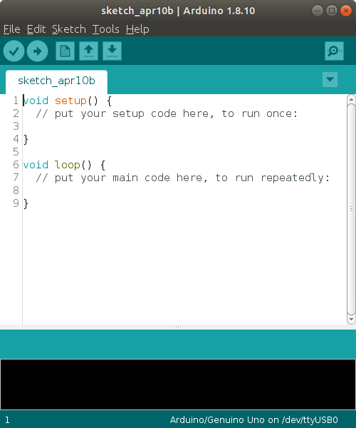
With the Arduino application installed, open it and you will see something like this.
Plug in your Arduino and it should be detected. But we need to make sure that we can use the board.
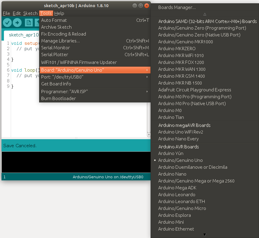
Click on Tools >> Board and select the Arduino board that you are using. I am using an Arduino Uno compatible.
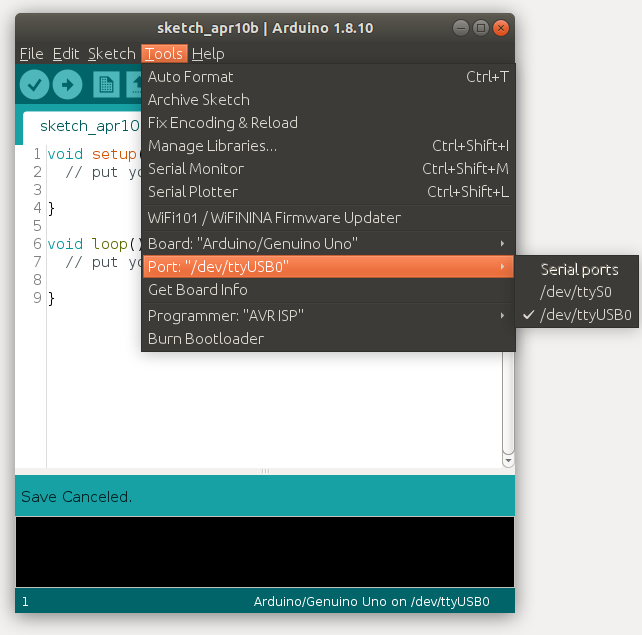
Next click on Tools >> Port and make sure that the correct port has been selected. On Linux this will most likely be /dev/ttyUSB0 or /dev/ttyACM0. For Windows users this will be COM and you can check this using the Hardware Monitor application built in to Windows.
Writing the code
We are going to write 19 lines of code for this project. So lets get started.
First we create three variables, called red,green,blue and these varaibles will store the Arduino pin number.
const int red = 1;
const int green = 2;
const int blue = 3;
Now I tell the Arduino that each of this pins will be outputs, and that current will flow from them to the LEDs.
void setup() {
  pinMode(red, OUTPUT);
  pinMode(green, OUTPUT);
  pinMode(blue, OUTPUT);
}
Next inside a loop we tell the Arduino to turn on and off the LEDs in a pattern.
The blue LED is turned off, and the red is turned on. Then pause for 1 second (1000 milliseconds)
void loop() {
  digitalWrite(blue, LOW);
  digitalWrite(red, HIGH);
  delay(1000);
Then we turn the red LED off and the green LED on, and another pause.
  digitalWrite(red, LOW);
  digitalWrite(green, HIGH);
  delay(1000);
The last part is where the green LED is turned off, and the blue LED turned on. With a final delay.
  digitalWrite(green, LOW);
  digitalWrite(blue, HIGH);
  delay(1000);
}
Arduino: Complete Code Listing
const int red = 1;
const int green = 2;
const int blue = 3;

void setup() {
  pinMode(red, OUTPUT);
  pinMode(green, OUTPUT);
  pinMode(blue, OUTPUT);
}

void loop() {
  digitalWrite(blue, LOW);
  digitalWrite(red, HIGH);
  delay(1000);
  digitalWrite(red, LOW);
  digitalWrite(green, HIGH);
  delay(1000);
  digitalWrite(green, LOW);
  digitalWrite(blue, HIGH);
  delay(1000);
}
Upload The Code
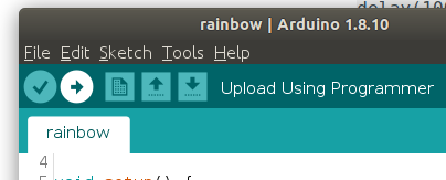
To upload the code to the Arduino, click on the arrow pointing to the right icon. This will check the code, and then upload. The Arduino will reset and your code is now running on the board.
Building the LEDs into a rainbow
With the code on the Arduino we can unplug it from the computer, and now build the LEDs into the rainbow.

First we make holes in the rainbow and for this we may need help from an adult / responsible person. Using a screwdriver or sharp point make a small hole in the colour which matches the colour of LEDs that you are using. Take care and go slowly, start with a small hole and then use a bigger tool to make the hole bigger. Check that your LEDs fit snuggly.
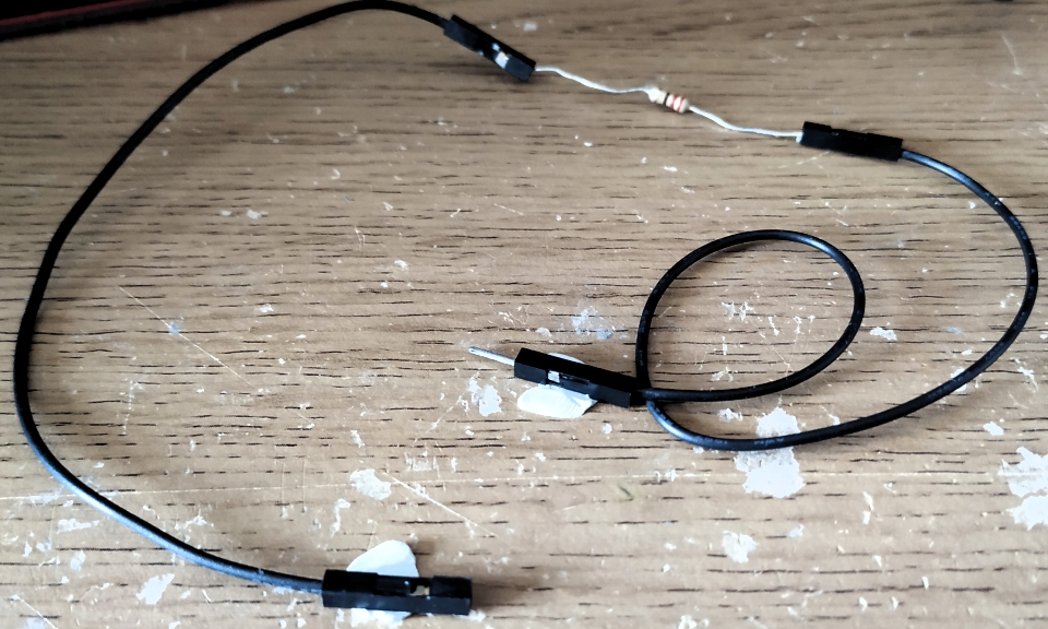
Next we take a male to female jumper wire, and a female to female jumper wire.
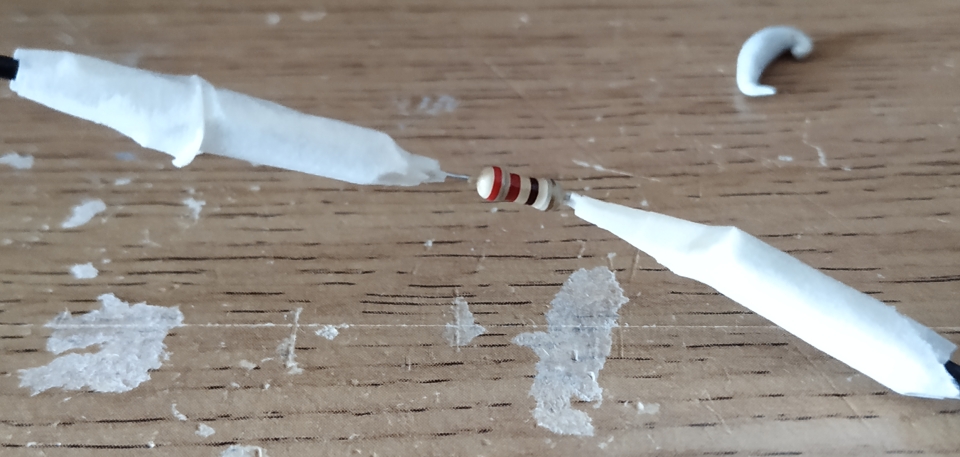
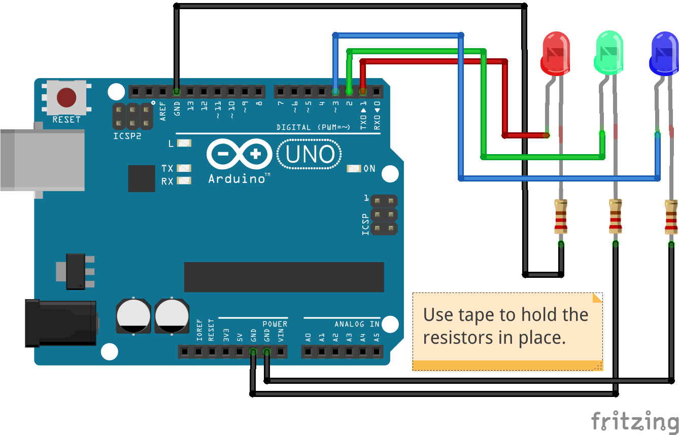
Pick up the female to male wire, and insert a 220 Ohm resistor into the female end. Use a little tape to hold it in place.
Attach the other end of the resistor into one end of the female to female jumper wire. Use more tape to secure it.
Insert the male end into a GND pin on your Arduino. Attach the female end to the short leg of the red LED.
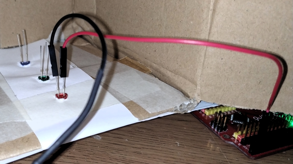
Next connect a male to female jumper wire from pin 1 of the Arduino to the long leg of the RED LED. We may need a little more tape to hold everything in place. Connect the Arduino to your computer and the red LED should turn on and off.
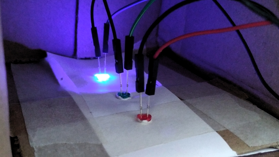
Repeat this process for the green (pin 2) and blue (pin 3) LEDs.
Ensuring that you test as each LED is connected.
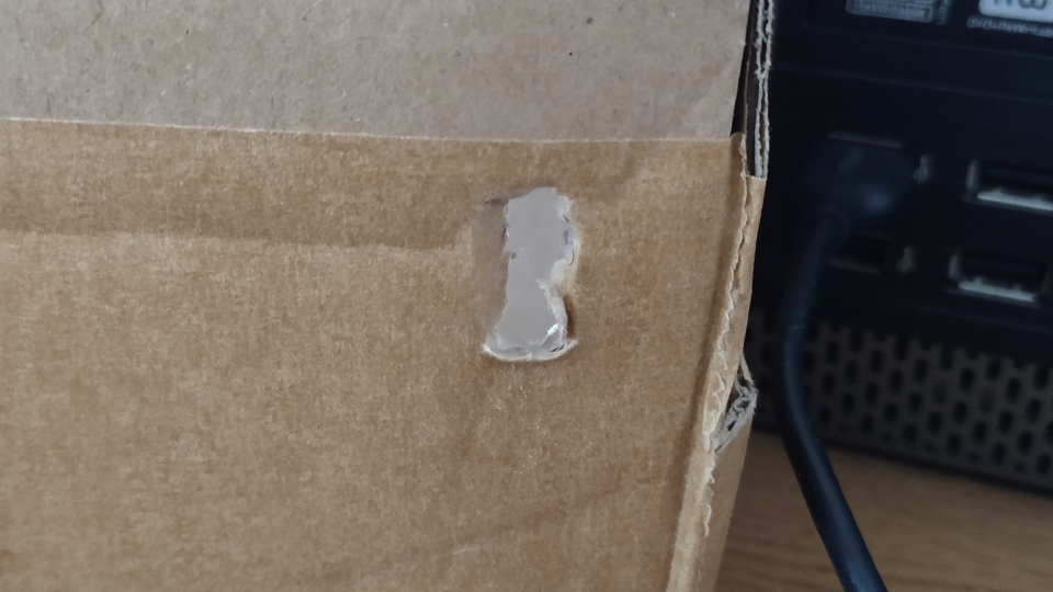
I carefully bodged a hole into the cardboard and fed a micro USB lead into the box, then I placed my Arduino inside and connected the power. Now the Arduino is hidden in the box, and the LEDs are lighting up for all to see.
CircuitPython Build
Software
The best way to use CircuitPython is using Mu made by Nicholas Tollervey. Mu is an easy to use Python editor that is made for beginners and it is totally free. Head over to the Mu website and follow the installation for your operating system.
Writing the code
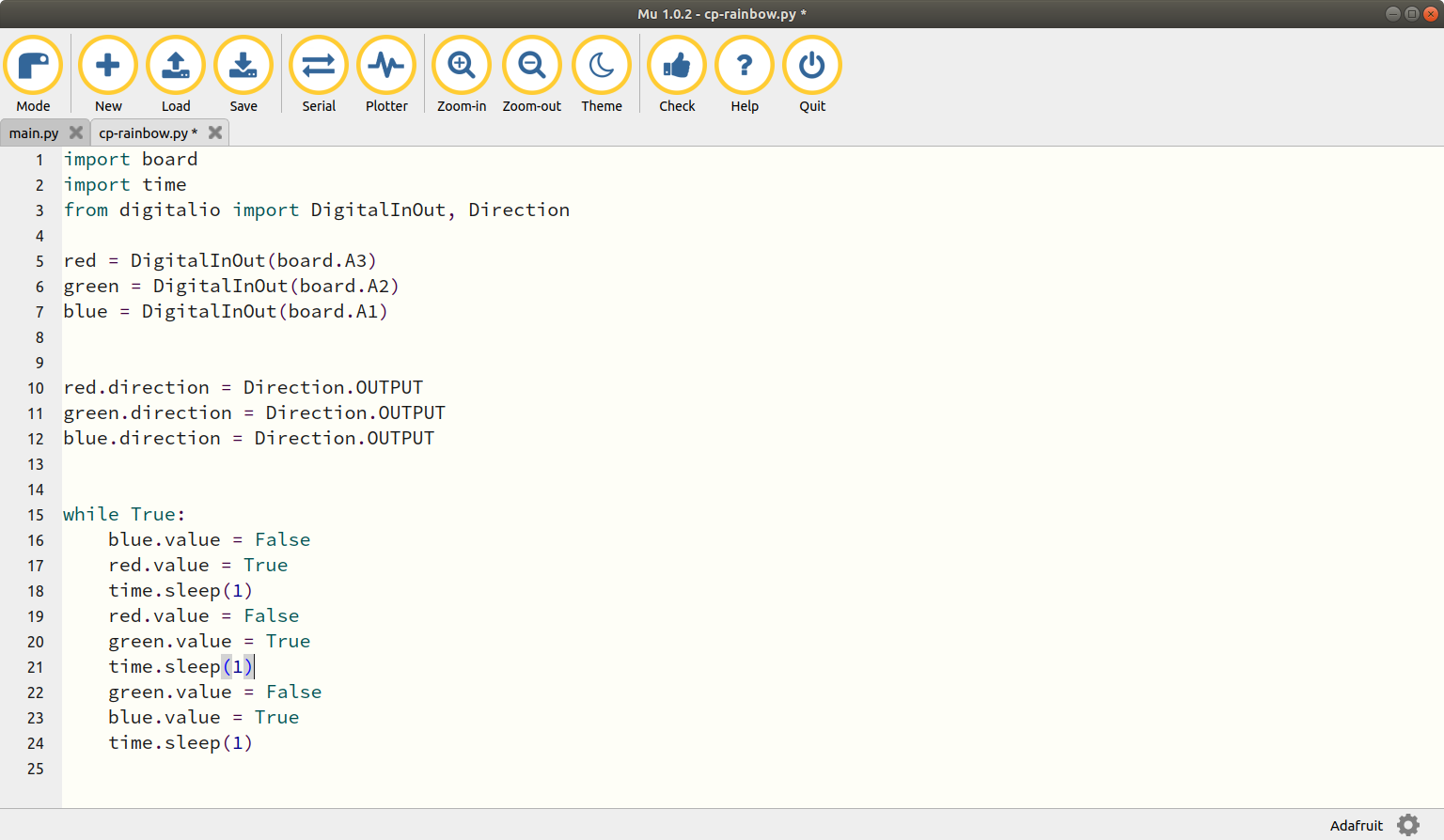
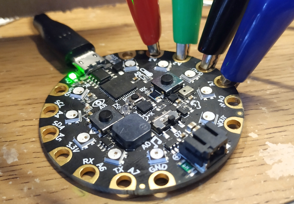
Open the Mu application and plug in your CircuitPython device. I am using a Circuit Playground Express which I will abbreviate to CPX.
We will be writing CircuitPython, which is a form of Python for microcontrollers. We start the code by importing a series of modules (libraries of pre-written code that enable us to quickly build the code.) The first module is board and this enables our code to talk to the CPX. The second module is time and we can use this to control the duration that LEDs are on / off. Lastly we import a module to control the digital setup of a GPIO pin.
import board
import time
from digitalio import DigitalInOut, Direction
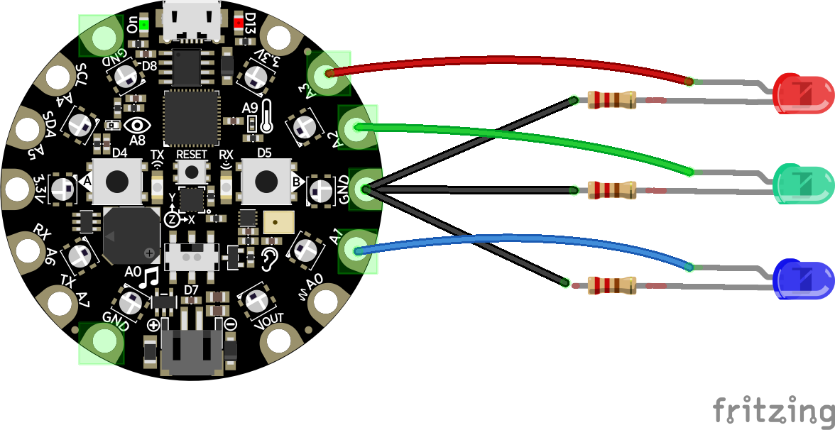
Next we create three variables which will represent the LEDs and to which GPIO pin they are connected. Red is connected to A3, Green to A2 and Blue to A1.
red = DigitalInOut(board.A3)
green = DigitalInOut(board.A2)
blue = DigitalInOut(board.A1)
We now need to tell the CPX that these LEDs are output devices and that we want current to flow to them so that they light up.
red.direction = Direction.OUTPUT
green.direction = Direction.OUTPUT
blue.direction = Direction.OUTPUT
On to the main loop and here we use a while True: loop to run the code forever. First we turn off the blue LED by setting its value to False then we turn the red led on by setting the value to True. A short pause of 1 second is then added to slowly control the LED sequence.
while True:
    blue.value = False
    red.value = True
    time.sleep(1)
The red LED is then turned off, green is turned on, and another sleep is used.
    red.value = False
    green.value = True
    time.sleep(1)
The last section of code will turn the green LED off, turn the blue LED on and then pause for 1 second.
    green.value = False
    blue.value = True
    time.sleep(1)
CircuitPython: Complete Code Listing
import board
import time
from digitalio import DigitalInOut, Direction

red = DigitalInOut(board.A3)
green = DigitalInOut(board.A2)
blue = DigitalInOut(board.A1)


red.direction = Direction.OUTPUT
green.direction = Direction.OUTPUT
blue.direction = Direction.OUTPUT


while True:
    blue.value = False
    red.value = True
    time.sleep(1)
    red.value = False
    green.value = True
    time.sleep(1)
    green.value = False
    blue.value = True
    time.sleep(1)
Save the code
Click on Save and select the CIRCUITPY device, in there is a file called main.py save and overwrite that file. The CPX will reboot and the code will start running. Now it is time to start building the LEDs into our rainbow.
Building the LEDs into a rainbow
With the code on our CPX we can unplug it from the computer, and now build the LEDs into the rainbow.
First we make holes in the rainbow and for this we may need help from an adult / responsible person. Using a screwdriver or sharp point make a small hole in the colour which matches the colour of LEDs that you are using. Take care and go slowly, start with a small hole and then use a bigger tool to make the hole bigger. Check that your LEDs fit snuggly.
Next we take a male to female jumper wire, and a female to female jumper wire.
Pick up the female to male wire, and insert a 220 Ohm resistor into the female end. Use a little tape to hold it in place.
Attach the other end of the resistor into one end of the female to female jumper wire. Use more tape to secure it.
Insert the male end into a crocodile clip and connect to the GND of the CPX. Attach the female end to the short leg of the red LED.
Next connect a crocodile clip from pin A0 of the CPX to the long leg of the RED LED. We may need a little more tape to hold everything in place. Connect the CPX to your computer and the red LED should turn on and off.
Repeat this process for the blue and green LEDs. Ensuring that you test as each LED is connected.
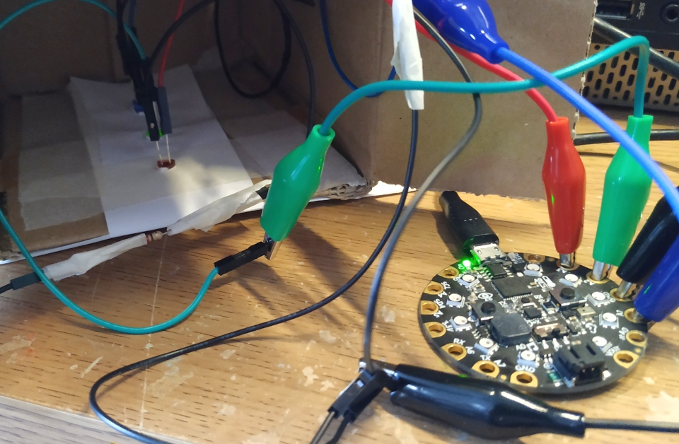
I carefully bodged a hole into the cardboard and fed a micro USB lead into the box, then I placed my CPX inside and connected the power.
Now the CPX is hidden in the box, and the LEDs are lighting up for all to see.
micro:bit Build
The best way to use MicroPython is using Mu made by Nicholas Tollervey. Mu is an easy to use Python editor that is made for beginners and it is totally free. Head over to the Mu website and follow the installation for your operating system.
Writing the code
Open the Mu application and plug in your micro:bit. Mu will detect and ask if we would like to switch to micro:bit mode, and yes we do.
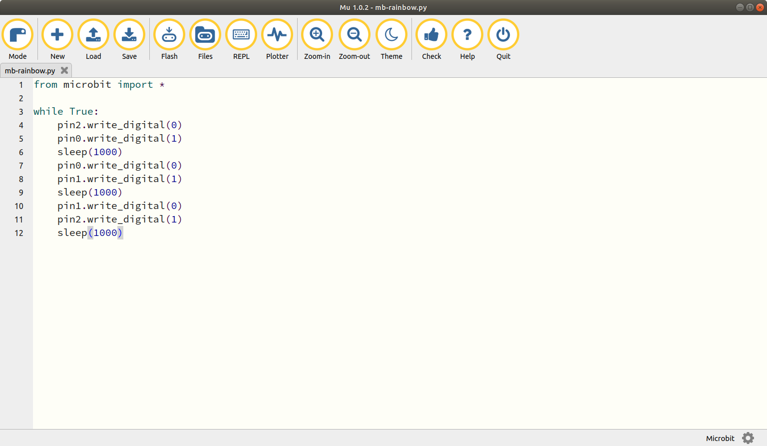
The micro:bit code is the easiest of the four, and we start by importing a module to enable our code to talk to the micro:bit.
from microbit import *
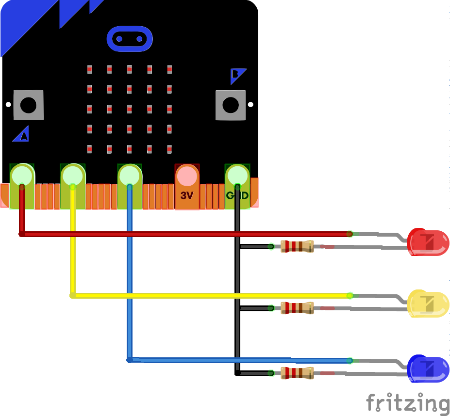
Now we go straight into the loop which will control the LEDs. In the loop we tell pin2 to turn off (0) and pin 0 to turn on. This turns the blue LED off, and the red LED on. Then we sleep for one second (1000 milliseconds.)
while True:
    pin2.write_digital(0)
    pin0.write_digital(1)
    sleep(1000)
To turn off the red LED, and turn on the green LED I turn pin0 off, and pin1 on. Then sleep for a second.
    pin0.write_digital(0)
    pin1.write_digital(1)
    sleep(1000)
Lastly to turn off the green LED and turn on the blue LED and then sleep for a second.
    pin1.write_digital(0)
    pin2.write_digital(1)
    sleep(1000)
micro:bit Complete Code Listing
from microbit import *

while True:
    pin2.write_digital(0)
    pin0.write_digital(1)
    sleep(1000)
    pin0.write_digital(0)
    pin1.write_digital(1)
    sleep(1000)
    pin1.write_digital(0)
    pin2.write_digital(1)
    sleep(1000)
Flash the code
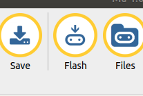
To send the code to the micro:bit we need to click on Flash and this will send the code to the micro:bit. We can see this happen as an LED on the rear of the micro:bit will flash.
Building the LEDs into a rainbow
With the code on our micro:bit we can unplug it from the computer, and now build the LEDs into the rainbow.
First we make holes in the rainbow and for this we may need help from an adult / responsible person. Using a screwdriver or sharp point make a small hole in the colour which matches the colour of LEDs that you are using. Take care and go slowly, start with a small hole and then use a bigger tool to make the hole bigger. Check that your LEDs fit snuggly.
Next we take a male to female jumper wire, and a female to female jumper wire.
Pick up the female to male wire, and insert a 220 Ohm resistor into the female end. Use a little tape to hold it in place.
Attach the other end of the resistor into one end of the female to female jumper wire. Use more tape to secure it.
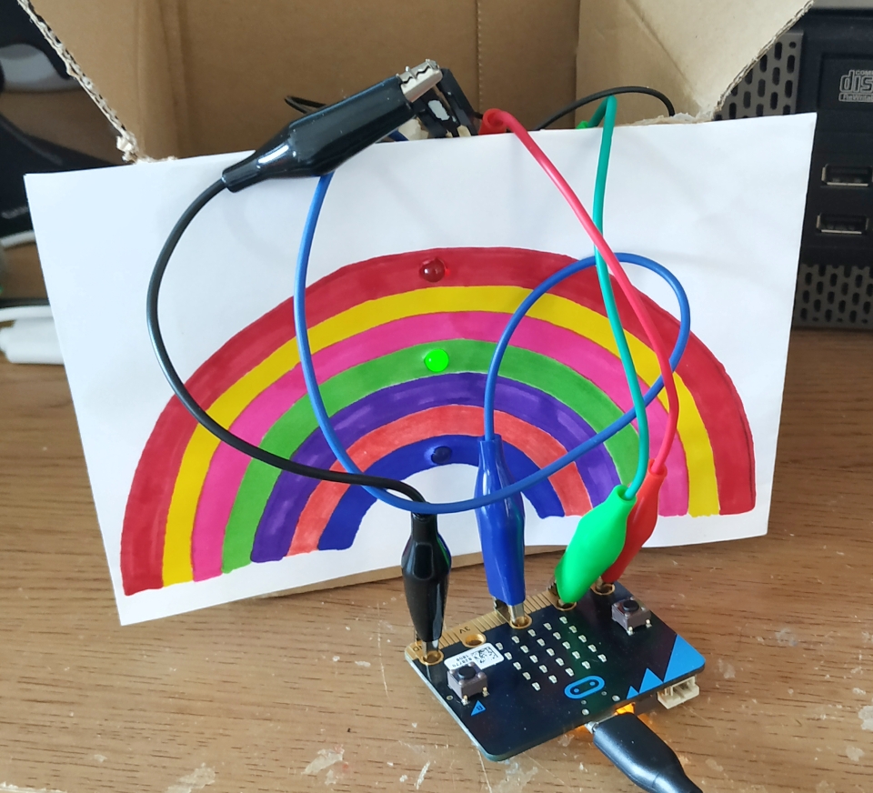
Insert the male end into a crocodile clip and connect to the GND of the micro:bit. Attach the female end to the short leg of the red LED.
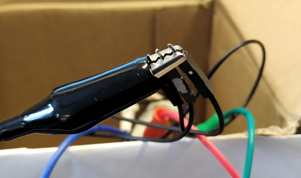
Next connect a crocodile clip from pin 0 of the micro:bit to the long leg of the RED LED. We may need a little more tape to hold everything in place. Connect the micro:bit to your computer and the red LED should turn on and off.
Repeat this process for the blue and green LEDs. Ensuring that you test as each LED is connected.
I carefully bodged a hole into the cardboard and fed a micro USB lead into the box, then I placed my micro:bit inside and connected the power.
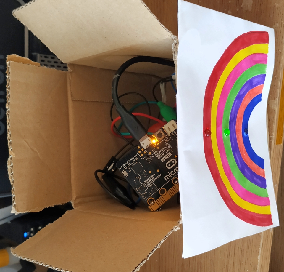
Now the micro:bit is hidden in the box, and the LEDs are lighting up for all to see.
Raspberry Pi Build
Software
We shall be using a Raspberry Pi 4 in this tutorial, but this project can be done with any model. Just make sure that you have the latest Raspbian operating system as it comes with Thonny, the Python editor that we shall be using to write the code.
Writing the code

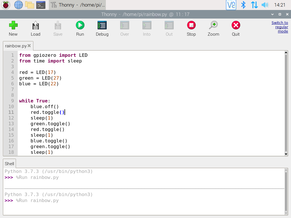
Open the Thonny application, found in the Programming menu.
In the new file we are going to write our Python code.
We start by importing two modules. The first is called GPIO Zero and it is a simple tool to control the GPIO using Python. From this module we import the LED class, which will enable us to directly control the LEDs. The next module is called time and from it we import the sleep function, which is used to add pauses to our code.
from gpiozero import LED
from time import sleep
We need to tell GPIO Zero where our LEDs are connected. The connections are made to GPIO 17 (red), 27 (green) and 22 (blue).
red = LED(17)
green = LED(27)
blue = LED(22)
Using a loop to continually run the code, we first turn off the blue LED and then use toggle() to turn the red LED on before we pause for 1 second.
while True:
    blue.off()
    red.toggle()
    sleep(1)
We then toggle the green LED on, and then use toggle on the red LED to turn the LED off. We then pause for another second.
    green.toggle()
    red.toggle()
    sleep(1)
Toggle?
The toggle function checks the current state of the LED. If the LED is on, then toggle will turn it off. If an LED is off, toggle will turn it on.
The last few lines of code will turn the blue LED on and then turn the green LED off. A final pause before the loop repeats.
    blue.toggle()
    green.toggle()
    sleep(1)
Raspberry Pi Complete Code Listing
from gpiozero import LED
from time import sleep

red = LED(17)
green = LED(27)
blue = LED(22)


while True:
    blue.off()
    red.toggle()
    sleep(1)
    green.toggle()
    red.toggle()
    sleep(1)
    blue.toggle()
    green.toggle()
    sleep(1)
Save the code

Save the code as rainbow.py and click Run.
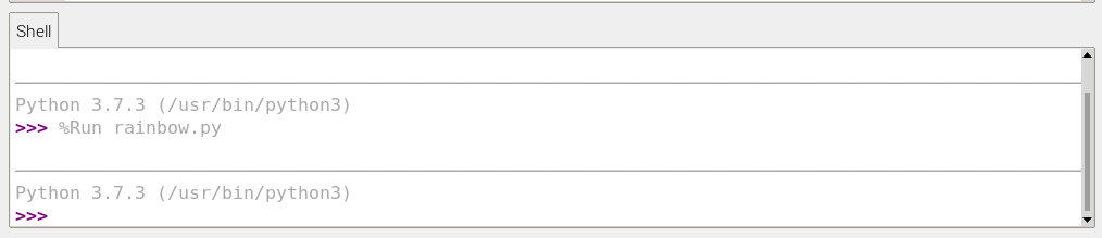
You will see the Python shell start the code, there should be no errors in the shell. If there are then we need to fix them.
Building the LEDs into a rainbow
With the code on our Raspberry Pi we can now build the LEDs into the rainbow.
First we make holes in the rainbow and for this we may need help from an adult / responsible person. Using a screwdriver or sharp point make a small hole in the colour which matches the colour of LEDs that you are using. Take care and go slowly, start with a small hole and then use a bigger tool to make the hole bigger. Check that your LEDs fit snuggly.
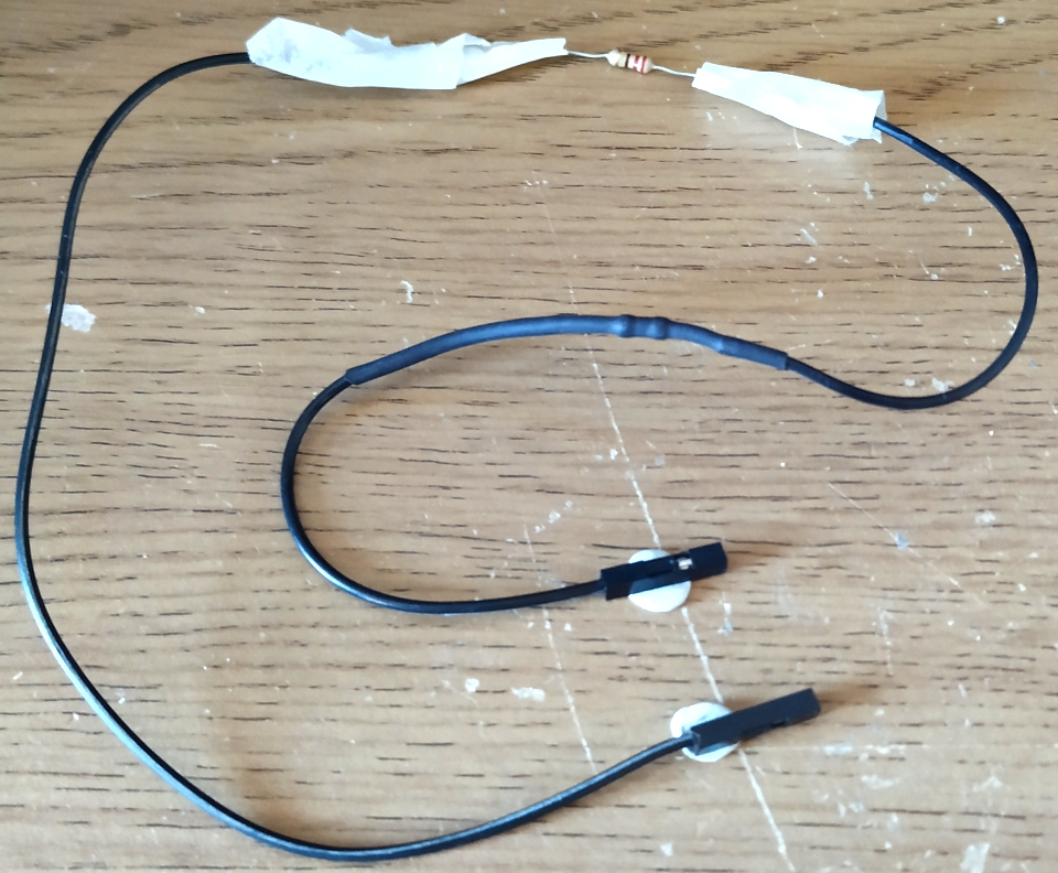
Next we take two female to female jumper wires and insert a 220 Ohm resistor into one end. Use a little tape to hold it in place.
Attach the other end of the resistor into one end of the other female to female jumper wire. Use more tape to secure it.
Connect one end to any of the GND pins of the Raspberry Pi. Attach the other end to the short leg of the red LED.
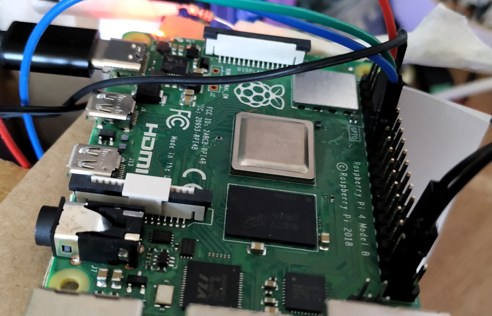
Next connect another female to female jumper wire from GPIO17 of the Raspberry Pi to the long leg of the RED LED. We may need a little more tape to hold everything in place. If your code is still running then the red LED should turn on and off.
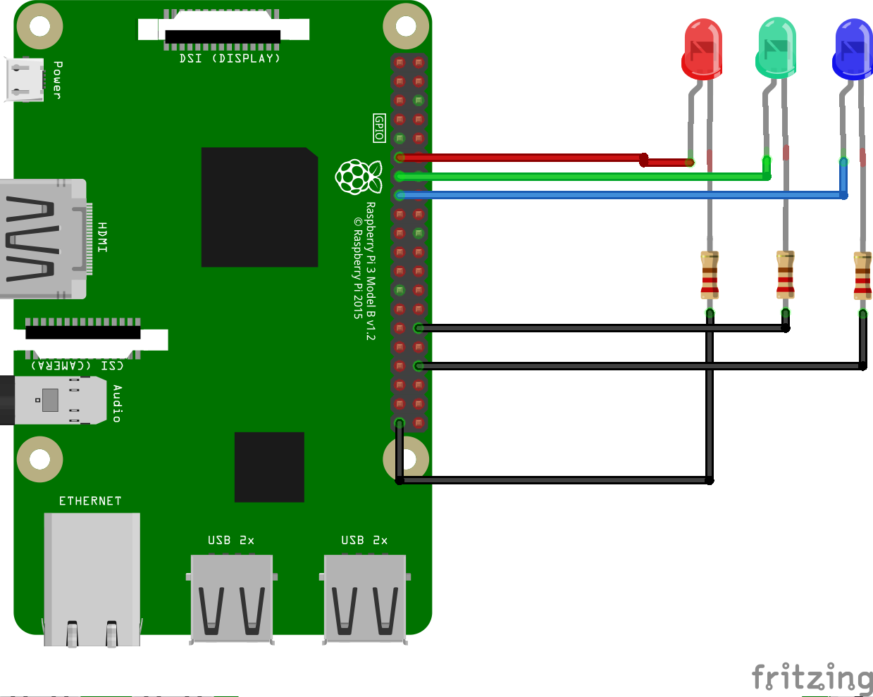
Repeat this precess for the blue and green LEDs. Ensuring that you test as each LED is connected.
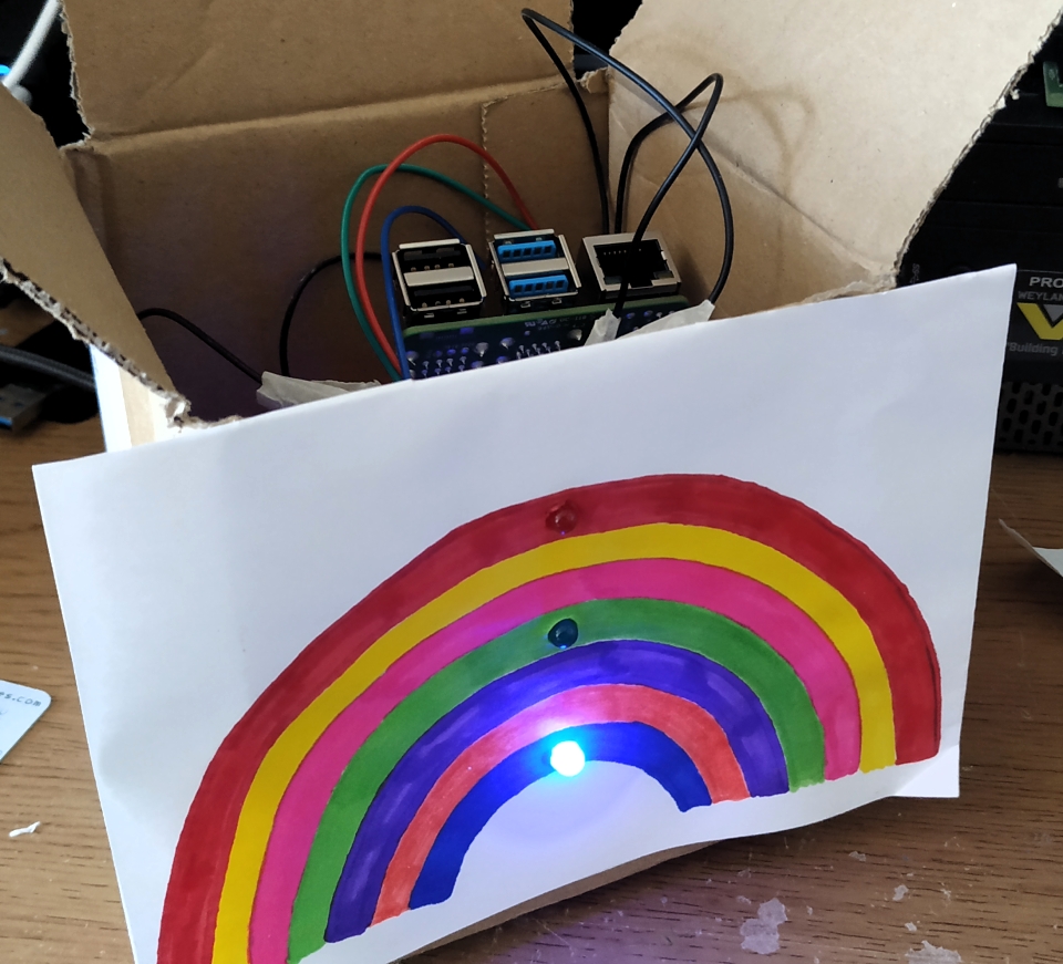
I carefully bodged a hole into the cardboard and fed a micro USB lead into the box, then I placed my Raspberry Pi inside and connected the power.
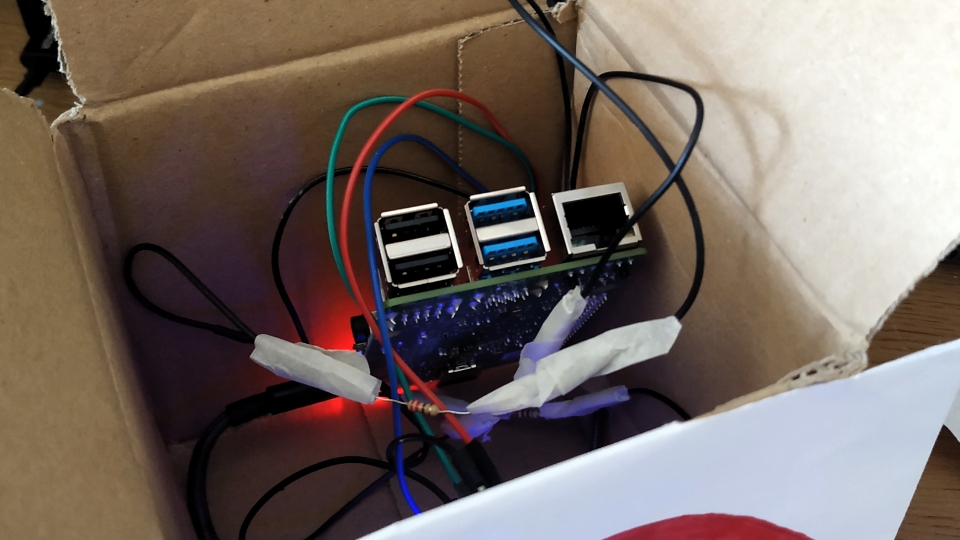
Now the Raspberry Pi is hidden in the box, and the LEDs are lighting up for all to see.
All done!
We've made a rainbow which will light up and show how much key workers mean to us!