micro:bit Infrared Timing Gate
In early March 2017 I, along with local hacker Dave Gallop were asked by St Mary Magdalen's Catholic Primary School to come along and help them build some supersonic race cars for the Bloodhound SSC project with teams of children designing, building and testing their designs using a wind tunnel app.
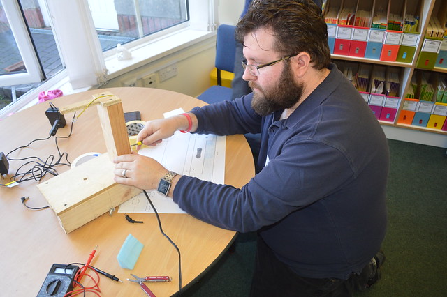
We (Dave) broke the foam cutter as the power supply got very hot...and then stopped working. So here is me fitting a new power supply, which Jan found in a box full of spare bits
We had great fun building the cars, Dave Gallop brought along his homemade foam cutter and we started to cut the cars from the block foam.
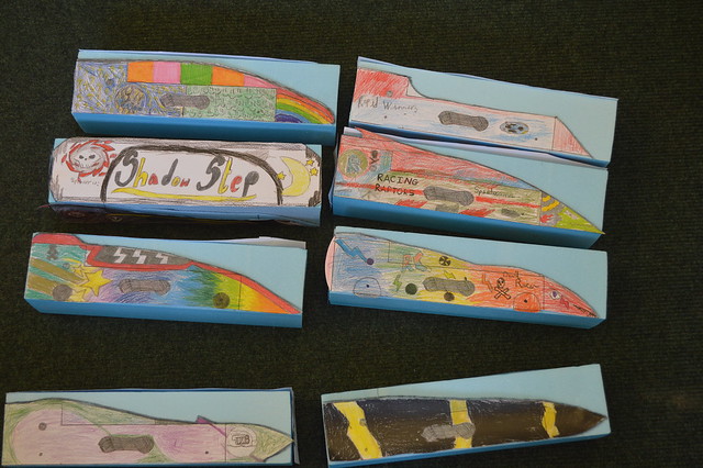
The kids made some fantastic cars!
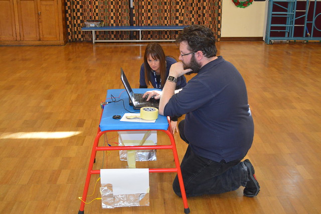
But...we needed to check how fast our cars could travel...so we needed a timing gate.
Blue Peter Build
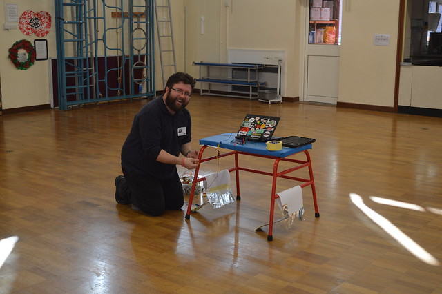
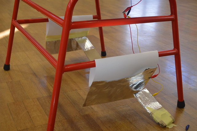
We didn't have the right kit to make a proper timing gate, but we made do with a series of cardboard, paper, glue and tin foil sensors that detected when the cars entered and left the timing rig.
My knees have gone and I can't get up #sysadminOLDMAN
For our next trick we shall build Tracy Island
Even the teachers had a go!
Making a better timing rig
So I thought about how I could make a better timing rig, and it struck me.
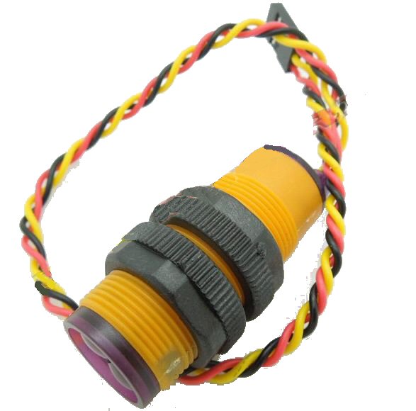
Infrared obstacle sensor from 4tronix
I have some infrared obstacle sensors that could be used as triggers for the gates...but they use 5V power and do not work with 3V power. (They also work really well with the Raspberry Pi)
So in order to use the sensor I had to test that it would work with an external power supply, and that the output pin, coloured yellow, output a voltage that was safe for the micro:bit...luckily it was as it produced an output of 3V, phew!
Here is the kit that I used
- 2 x Infrared obstacle sensors
- 1 x microbit
- 1 x External 5V power supply for the sensors
- Assorted wires to connect sensors to micro:bit and to external power supply. I used a Proto Pic exhi:bit (blog post to be written on this great board) to prototype and connect it all up, but for the final version I will build a simple protoboard "PCB". The exhi:bit it is not needed as you can use crocodile clips to connect the wires of the circuit, just make sure they don't short each other out.
- 1 x micro USB lead to connect your micro:bit to your computer.
The circuit

As you can see in the diagram the black wire (Ground / GND) from the battery (our power supply for the sensors) is connected to the GND pin for each sensor and to the GND pin of the micro:bit. This creates common ground and enables everything to work correctly. If we didn't do this then we would have an unreliable sensor.
I also thought about the distance between the two sensors. For the Blue Peter rig we used a vaulting horse which was 80cm between the gates. For the new version I am going for 1 metre between sensors. I'll use Ethernet cable to connect everything together...as I have hundreds of metres in the loft!
#sysadminHOARDER
Once you know the distance and the time of the run, it is a simple bit of maths to calculate the speed of the car.
Code for the rig
I wrote the code in Micro Python, using the Mu editor. I have it installed on my laptop, but you can also use the online version.
I start the code by importing the microbit library, enabling me to use the micro:bit and its integrated components.
from microbit import *
I then used a loop to constantly run the code.
while True:
Then I used a conditional test to check if the start gate sensor had been triggered. The sensors constantly produce a high signal, in other words send current down the output wire connected to pin 0. Once something triggers the sensor, the signal goes low, no power is sent down the output wire and pin 0 receives 0V this triggers the timer to start.
if pin0.read_digital() == 0:
The timer uses a start_time variable,which is created by asking the micro:bit "How long have you been running for?" This time is then stored in the variable.
start_time = running_time()
Next I created an else if condition. Python calls these elif. This test checks to see if the end gate sensor has been triggered and if so then it records the end_time
    elif pin1.read_digital() == 0:
        end_time = running_time()
Still inside the elif condition, I then created another variable called race_time and this variable is used to store the product of an equation. This equation first subtracts the start_time from the end_time and then divides it by 1000, this is because the micro:bit uses milliseconds for timing and by dividing by 1000 we can see the time in seconds.
race_time = (end_time - start_time) / 1000
For the last section of code, the race_time data is printed to the Python shell Repl and then the code waits for half a second (500ms) before enabling the micro:bit to repeat the code sequence.
Complete Code Listing
from microbit import *
while True:
    if pin0.read_digital() == 0:
        start_time = running_time()
    elif pin1.read_digital() == 0:
        end_time = running_time()
        race_time = (end_time - start_time) / 1000
        print(race_time)
        sleep(500)
Code Download
I've provided all of the code and a high resolution circuit diagram that you are free to download and use in your next project.
Extension Activity
I had an idea...the micro:bit has a radio function that can be used to communicate between micro:bits. I could have one at the timing rig, that sends the time to another micro:bit that is connected to my laptop, and using Python I could connect using a serial interface and record the data to an external file for use later. I might try this but for now I am happy with the existing setup.
Well done team!
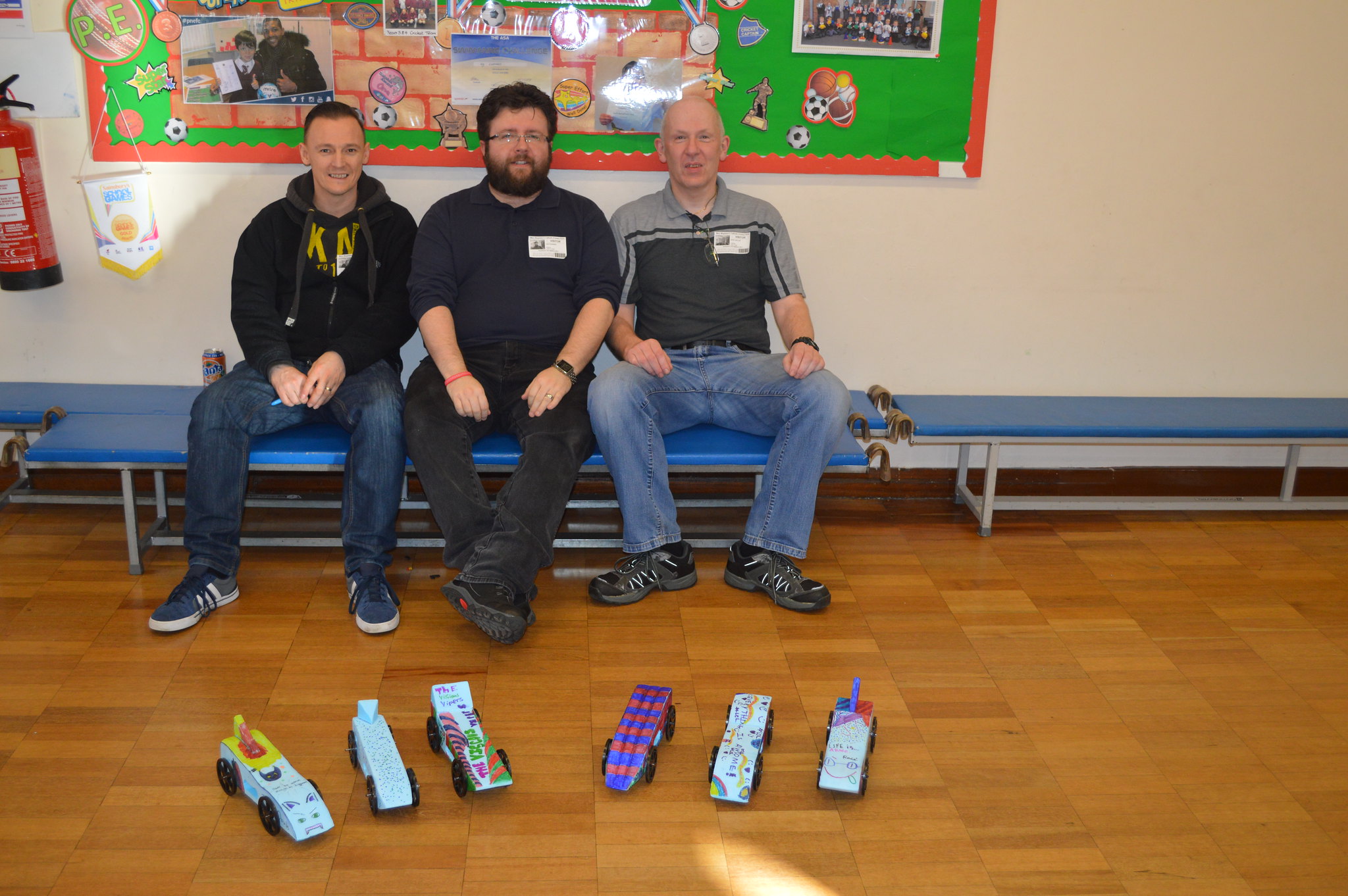
Dave Lowe, Les Pounder and Dave Gallop celebrate, with a sit down
Photo credit
All of the photos in this blogpost were kindly provided by Dave Gallop. Thanks Dave!