Microcontroller Monday - Control an L298N motor controller with micro:bit
I love the L298N motor controller, it was the first motor controller that I was able to understand and use. It enabled me to make things move and then create my first robot!
If you like what you read...
Would you like to buy me a cup of coffee? It helps me to pay for hosting this blog, and to buy stuff to hack from Poundshops / Dollar Stores which are used in free projects on this blog. Thanks!
What prompted this post?
Chris Penn on Twitter asked...
"@biglesp know of any cost effective motor controllers that work with Microbits"
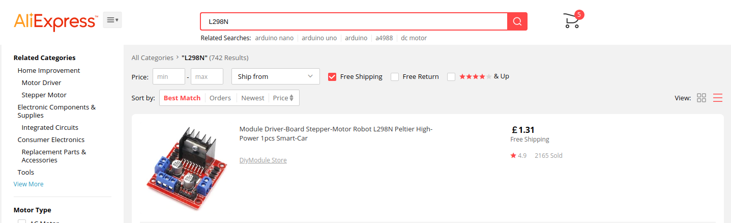
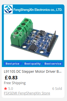
And being a geek I was able to suggest the L298N (£1.31 from Aliexpress at the time of writing) and the L9110S (83p from Aliexpress again) motor controllers. Chris went and purchased an L298N and I said that I would write a quick post to help him get setup!
So what do we do now?
For this project you will need
- A computer with Internet access
- A micro:bit
- An L298N motor controller
- 4 x AA Batteries
- 4 x AA battery holder
- A DC Motor
- Some wires to make connections between the micro:bit and L298N
You can see that I am using a 4tronix BIT:170 breadboard adapter to work with the project. This is not essential, you can snip, hack and create your own connections. I used it to make this tutorial a little cleaer in the video.
Coding the project
For this project I had to use a micro:bit, and I wanted to write some really simple demo code. So I went to the micro:bit website and wrote the code using the MakeCode editor.
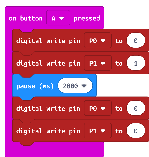
As you can see in the code above, I use on button A pressed from Input and then I click on Advanced to show the Pins blocks. I want the digital write pin P0 to 0 block, and I take four of them and place them inside the input block. Then I change P0 to P1 and 0 to 1 accordingly. In the middle of these blocks I place pause (ms) from the Basic blocks, and use that to add a delay.
So the code will
- When Button A is pressed
- Turn off P0 and turn on P1 at the same time
- Pause for 2000ms (2 Seconds)
- Turn off pins P0 and P1
So what will the code control?
Good question! Pins 0 and 1 of the micro:bit will be connected to an L298N motor controller. But we need to build the circuit, luckily I have a design for you to follow.
The L298N
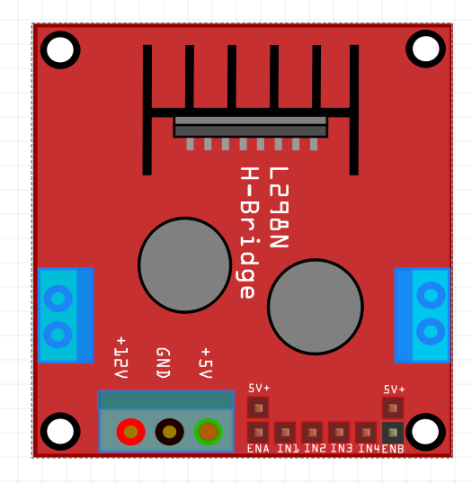
This is a simple motor controller but it is mighty! At the bottom of the image, we can see +12V GND and +5V.
- +12V is where power comes in to the L298N.
- GND is a Ground (-) connection from our batteries, and to the GND pin of a micro:bit.
- +5V supplies 5V output which can be used to power a 5V micro controller Not a micro:bit!
Next to these we can see EN, IN1, IN2, IN3, IN4, ENB. I'm going to ignore ENA and ENB for this post as we don't use them.
IN1 to IN4 are inputs which when turned on / off and used to control the corresponding outputs on the L298N. These outputs are the blue screw terminals on the edge of the board. They are marked OUT1 to OUT4.
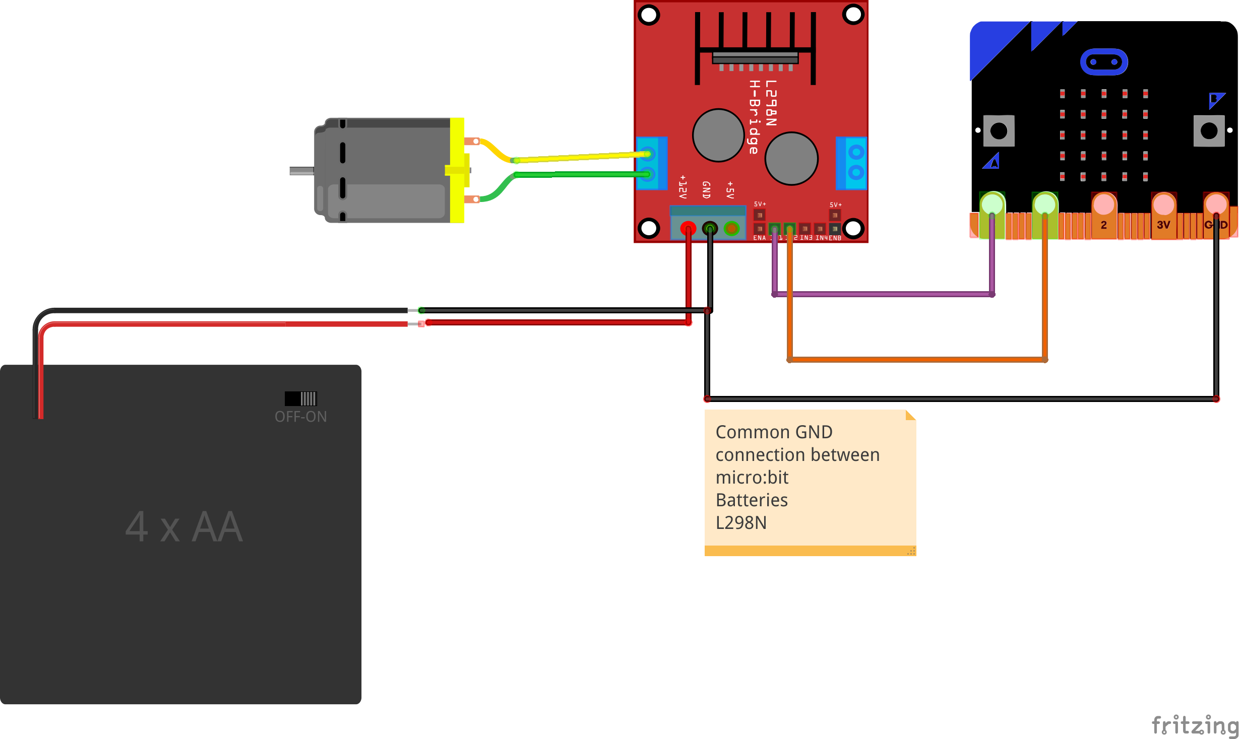
Lets step through the circuit, starting with the connections between the micro:bit and L298N.
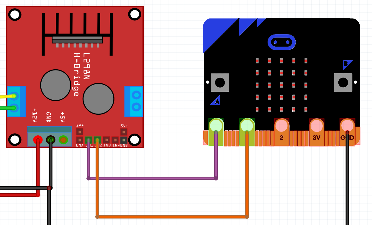
Pin 0 and 1 from our micro:bit are connected to IN1 and IN2 (respectively) on the L298N. So when the code is run, the state of Pin 0 and 1 changes, this in turn triggers the L298N motor controller to spin the motor.
We also connect the GND pin of the micro:bit ito the GND of the L298N.
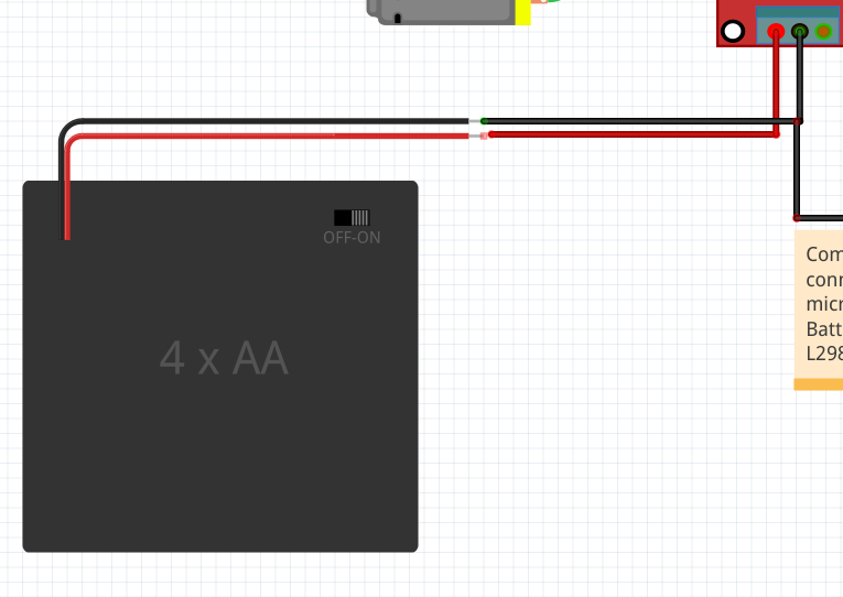
The AA battery pack connects directly to the L298N. With the red wire (6v) connecting to the +12V terminal of the L298N. The black wire (GND, -) connects to the GND terminal on the L298N.
It is important that the GND of the L298N, micro:bit and batteries is joined together. This creates a common ground which refers to a single 0V reference, from which all voltages in the circuit are measured. If you don't do this, then the motor may spin erratically, or just not work!
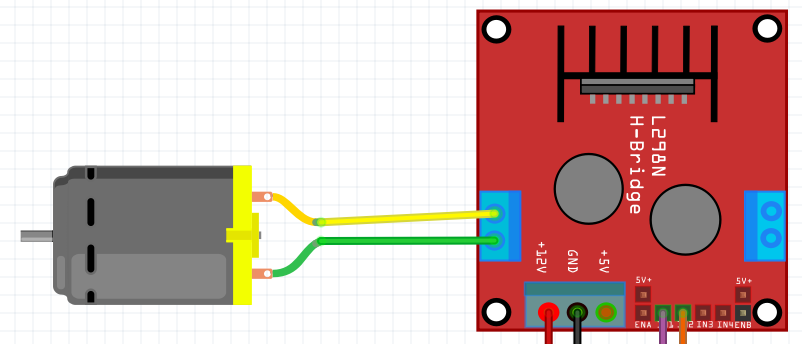
The last connection to make is from OUT1 and OUT2 to a DC motor. At this stage just connect the motor. If it spins the wrong way in testing, reverse the wires :)
Flash the code on to the micro:bit and get some batteries!
Pressing A on the micro:bit will now trigger the motor to spin for two seconds, then stop! You've done it! You are only a few steps away from building a robot with micro:bit! Enjoy and...
Happy Hacking!
BONUS CONTENT - Precise Speed Control!
Yup! Just use analog write instead. pic.twitter.com/qcjoEeXBaT
— biglesp (@biglesp) September 9, 2019
Chris asked if the speed can be controlled?
Well yes it can! Changing the code to this....
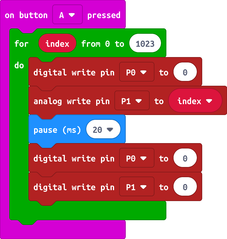
Will create a for loop that will increase the speed from 0 to 1023 (FULL POWER!!!) every 20ms.