Tooling Tuesday - 315MHz Transmitter & Receiver
A hardware themed blog post this week, a cheap 315MHz kit to remotely control your projects.
So what is it?

The XD-YK04 is a 315MHz receiver that has four outputs. These outputs can be connected to a 5V compliant microcontroller (Arduino Uno used to test in this post) and used to trigger events.
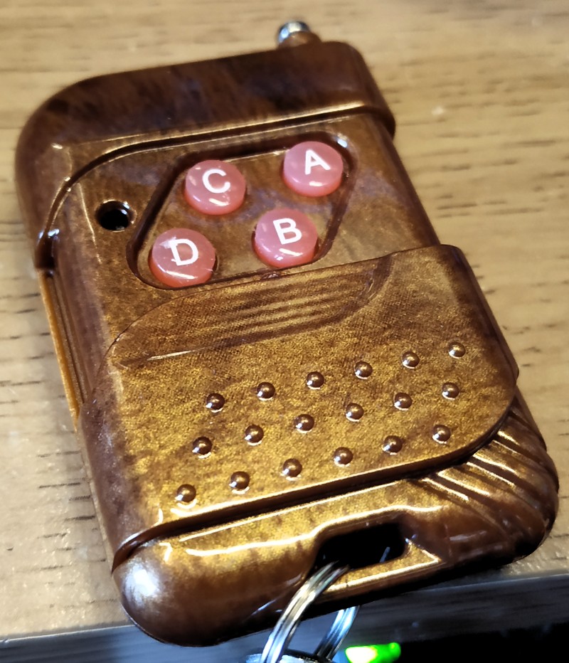
It uses a transmitter with four buttons marked A to D to correspond to the four outputs on the board (D0 to D3). So if we press A then D0 will activate, press D and D3 activates.
So how much?
I got mine from ABX Labs at Liverpool Makefest and if you want to pick up some "electronic goodies" take a look at his eBay store as he has some interesting bargains (FYI I'm not getting anything to say that, Dave (ABX) offers a good selection of unusual electronics bits and pieces.) But you can pick them up for around £1.71 on Aliexpress
Is this 3V logic compatible?
If you are a Pi user then out of the box this receiver is not compatible as it requires 5V and the output pins output 5V. You could use a voltage divider to reduce the 5v to 3V or use a transistor to act as a switch which is closed when the output if pulled HIGH.
So how do I use it?
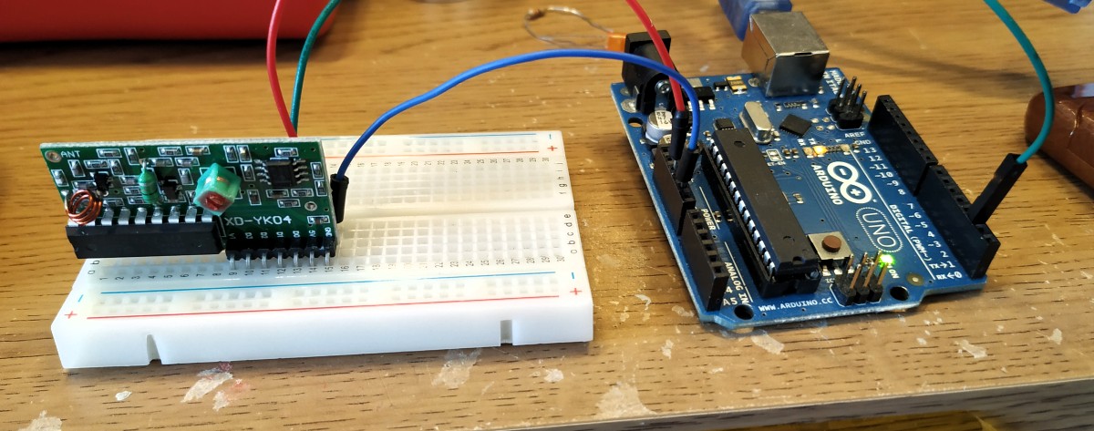
The receiver connects to your 5V microcontrollers 5V and GND pins, ensuring that the receiver has power. Then we connect an output pin, in this example D0, which maps to button A on the transmitter incidentally, to Pin 2 of an Arduino Uno.
In the Arduino IDE I used the DigitalReadSerial sketch, found in File >> Examples >> Basic as our test code. Typically this code looks for momentary switches, pushbuttons etc
Here is the code for you to review.
/*
  DigitalReadSerial

  Reads a digital input on pin 2, prints the result to the Serial Monitor

  This example code is in the public domain.

  http://www.arduino.cc/en/Tutorial/DigitalReadSerial
*/

// digital pin 2 has a pushbutton attached to it. Give it a name:
int pushButton = 2;

// the setup routine runs once when you press reset:
void setup() {
  // initialize serial communication at 9600 bits per second:
  Serial.begin(9600);
  // make the pushbutton's pin an input:
  pinMode(pushButton, INPUT);
}

// the loop routine runs over and over again forever:
void loop() {
  // read the input pin:
  int buttonState = digitalRead(pushButton);
  // print out the state of the button:
  Serial.println(buttonState);
  delay(1);        // delay in between reads for stability
}
The last line shows delay(1); which adds a very short delay between reading the pin state. I changed this to delay(100); as it made reading the serial monitor much easier.
So I flashed the code on to the Arduino, opened the serial monitor and saw the serial output stream up the screen. Initially this shows 0 but when I pressed the button on the transmitter it pulled D0 on the receiver to HIGH and this printed 1 to the serial monitor, proving it works!
This is not the most sophisticated piece of kit, but it is fun and easy to work with.