Friday Fun: Circuit Py-FUN!!!
This time we use the new Adafruit PyPortal to make a conference badge! The code for this project is based on Katnii's excellent PyPortal NeoPixel Color Picker
Conference badge?
I go to a fair few events in the year and each time delegates are given a sticker / badge to help everyone identify each other. But I wanted to make something a little more geeky / nerdy / techy!
So what are we doing?
Creating a conference badge that will act as a digital business card. It will have our logo, a picture of us or a project, and then a QR code containing our contact details (This is called a VCard and with it we can instantly drop a contact on to someones phone.)
So what are we using?
Adafruit's PyPortal is an Internet of Things (IoT) device that has WiFi, a 70mm by 50mm 320x240 resolution touchscreen, light sensor, temperature sensor, Neopixel, microSD slot and a speaker.
Powered by an ATSAMD51J20 CPU and with wireless connectivity provided by an ESP32 this is a lot of power in a small board. Smaller than a Pi Zero W and Hyperpixel screen!
To build this project you will need
- An Adafruit PyPortal
- The latest CircuitPython release
- A computer running Mu, an easy to use Python editor that supports Circuit Python.
- A USB battery
- Lanyard
Flashing the latest CircuitPython to PyPortal
This is not strictly necessary but it will ensure that we have the latest software release. Download the latest release, it will be a .UF2 file. Now to update the PyPortal we first need to press the RESET button on the back of the board twice! To get the timing right will take a few attempts. But when you do, you will see a new drive appear in your file manager / Windows Explorer called PORTALBOOT copy the .UF2 to this drive and wait for it to reboot. That's it!
Get the latest libraries
PyPortal / CircuitPython has lots of pre-written code libraries. They enable us to easily work with the hardware and sensors present on the many boards in the range. Download the latest libraries for the version of CircuitPython you are using. At the time of writing this was 4.x.
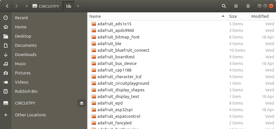
Once they are downloaded, extract the file to somewhere safe on your computer, and then copy those files to the PyPortal USB drive, specifically the CIRCUITPY/lib/ directory. This may take a while.
Writing the code
Firstly connect your PyPortal to your computer using a micro USB lead. PyPortal will appear as a USB flash drive, which means that we can save directly to it. But remember to make a backup of your code, just in case!
Open Mu
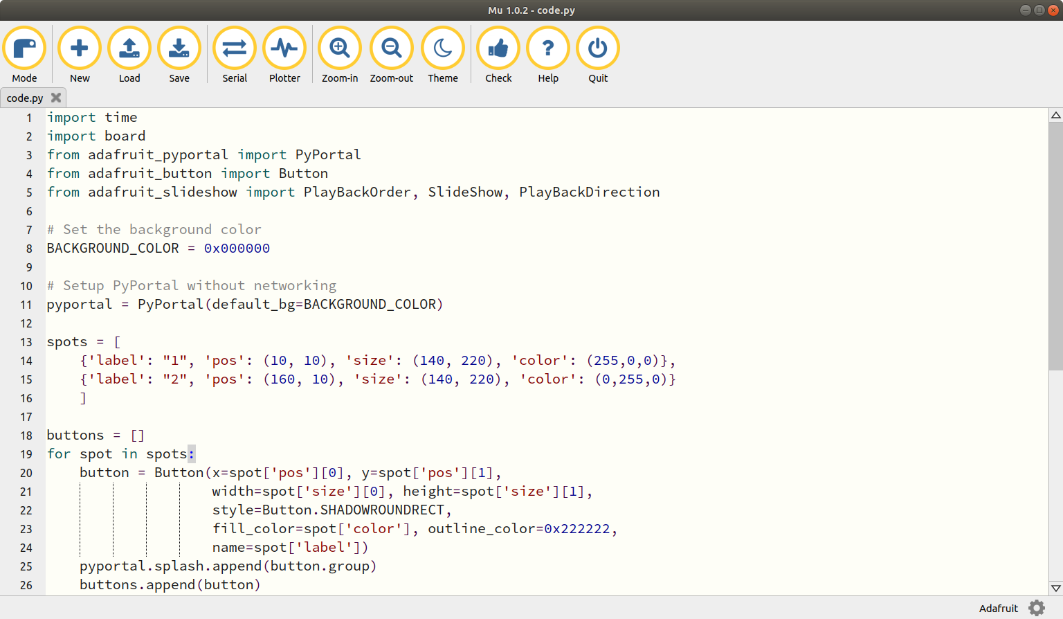
Open the Mu application and it should auto detect that we are using a CircuitPython board and display a dialog box asking us to switch to Adafruit Mode. Select Yes and you will now see in the bottom right of the screen that we are in Adafruit mode.
If this doesn't happen, then click on the Mode button in the menu and select Adafruit CircuitPython.
We start our code by first importing five libraries of pre-written CircuitPython. These libraries reference the files that we copied over earlier.
- First we import
timeto control the speed / pace of the project. - Next we import
boardto access the hardware. - The
PyPortallibrary enables us to directly access the PyPortal hardware with a specific library. Buttonis used to capture user input.adafruit_slideshowis the main tool to view images on the screen, and control playback direction and order.
import time
import board
from adafruit_pyportal import PyPortal
from adafruit_button import Button
from adafruit_slideshow import PlayBackOrder, SlideShow, PlayBackDirection
Moving on and we next create a variable called BACKGROUND_COLOR and in there we store the hex value for black 0x000000 so that we have a black screen on which to draw our images.
BACKGROUND_COLOR = 0x000000
Now we create an object called pyportal and use it to set the background colour to black using our variable.
pyportal = PyPortal(default_bg=BACKGROUND_COLOR)
For the next few lines of code we create a list called spots and in there we store two dictionaries which will store the attributes for two buttons. To create the list we give it a name, and the use [ to start creating the contents.
spots = [
Inside the spots list are two dictionaries which are used to contain the configuration of two hidden buttons on the touchscreen.
Lets take a look at the first dictionary in detail.
{'label': "1", 'pos': (10, 10), 'size': (140, 220), 'color': (255,0,0)},
The first item is called label and that is used to identify the button.
Next we see pos and this holds a tuple which contains the X and Y position where the button starts. In this case it starts 10 pixels in from the top left corner, and 10 pixels down from the same corner.
To set the size of the button we again use a tuple and this uses the same X and Y format. But this time the value given are for the size in pixels of the button, and not their placement.
The last item in the dictionary is color and this stores another tuple which provides the RGB colour code for red.
Tuple?
There are many ways to store data, variables, lists and dictionaries are the most obvious, but what about tuples? Well a tuple is similar to a list, in that it stores data using an index (starting at zero) and we can get data from a tuple by calling the tuples name and the position for the data that we want. But unlike a list, tuples cannot be modified (appended) and so if we wish to change the contents of a tuple, we have to destroy it and create a new tuple with the same name. Tuples are handy for comma separated values, such as the RGB colour codes used in this project.
Here is the code for the second dictionary, and to correctly close the spots list with a ].
    {'label': "2", 'pos': (160, 10), 'size': (140, 220), 'color': (0,255,0)}
    ]
The next line of code creates an empty list called buttons which we shall be using next.
buttons = []
Using a for loop to go through each item in the list spots we create buttons using the Button library that we imported earlier.
for spot in spots:
So we start by instructing the code where to find the X x=spot['pos'][0] and Y y=spot['pos'][1] position data. Then we move on to retrieve the button width width=spot['size'][0] and then the height height=spot['size'][1]. Moving on and the next option is style and this controls how our button looks. In this case Katnii has chosen to create a rounded rectangle with a drop shadow effect style=Button.SHADOWROUNDRECT. The final lines of code to create the button is to fill the button with our chosen colour fill_color=spot['color'] and set the outline colour to an off black outline_color=0x222222 then to give the button a name name=spot['label'].
Here is that code in full
    button = Button(x=spot['pos'][0], y=spot['pos'][1],
                    width=spot['size'][0], height=spot['size'][1],
                    style=Button.SHADOWROUNDRECT,
                    fill_color=spot['color'], outline_color=0x222222,
                    name=spot['label'])
The next line of code control our mode which is how we can detect and react to button presses. Right now we store 0 in mode.
mode = 0
In order to use the adafruit_slideshow library we first need to create an object called slideshow and in there we store a few configurations options. We instruct the library to use the built in touchscreen board.DISPLAY and that we are storing the images in the root of the CIRCUITPY drive folder="/". We also tell the slideshow that we wish to loop the images so that when we get to the end they go back to the start loop=Trueand to control the playback order we set it to alphabetical order=PlayBackOrder.ALPHABETICAL. The next configuration is called dwell and it instructs the slideshow to pause when an image is displayed dwell=0. The final two configuration steps are to add a fade between images fade_effect=True which can be turned off using False. Lastly we tell the slideshow not to auto advance through images auto_advance=False.
Here is the code in full for this line.
slideshow = SlideShow(board.DISPLAY, folder="/",
                      loop=True, order=PlayBackOrder.ALPHABETICAL, dwell=0, e, auto_advance=False)
We are now into the main loop of the code, and for this we need to use a while True loop so that the code is constantly running.
while True:
Inside the loop we first create an object called touch and in there we store the output when checking to see if we have pressed the screen.
touch = pyportal.touchscreen.touch_point
We then use that object in a conditional test that will check the contents. If the screen has been pressed over one of the rectangles we have created then it will print the output to the Serial console (Python REPL) for debug.
    if touch:
        for button in buttons:
            if button.contains(touch):
                print("Touched", button.name)
So how do we know which button was pressed? Well another conditional test is used and if the mode is 0, that means the left button (red) has been pressed and so we activate this condition. First we print "FORWARD" to the Serial console, then change the direction in which we move through the images to forward. Then we advance by one image.
                if mode == 0:
                    print("FORWARD")
                    slideshow.direction = PlayBackDirection.FORWARD
                    slideshow.advance()
But if we press the other rectangle then it will move us backward through the images.
                elif mode == 1:
                    print("REVERSE")
                    slideshow.direction = PlayBackDirection.BACKWARD
                    slideshow.advance()
The next line is a break which will get us out of the mode check conditional test and back into the test to see if any button has been pressed.
break
The last line of code is outside of all the conditional tests and is the last line of the while True loop that we created earlier. It adds an extremely short delay to the code, just enough time to detect a button press, but not too long so that it detects multiples pressed.
time.sleep(0.05)
Complete Code Listing
Save the code to the PyPortal
Save the code to your PyPortal using the filename code.py as this will be autorun when PyPortal boots.
Images!!
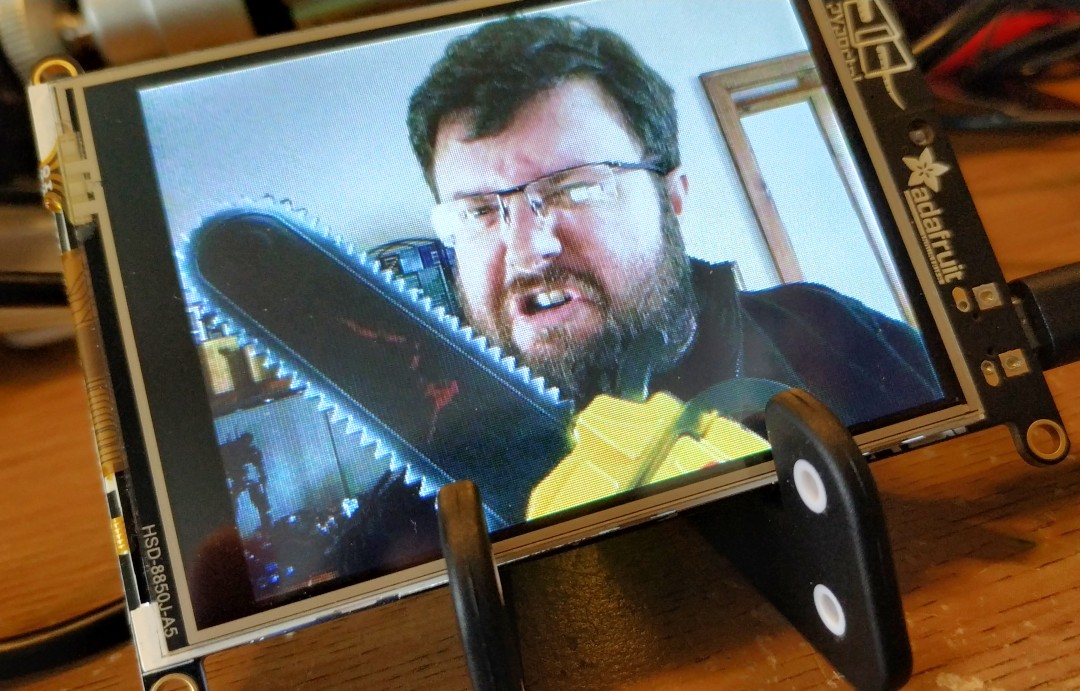
The PyPortal screen will show a series of images. Each time we press a side of the screen it will go forwards / backwards through the images.
Images are sorted alphabetically based on the first letter in their name, so A, B , C etc.
Using your favourite image editor (Photoshop, MSPaint, GIMP etc) create or convert images to 320x240 resolution, and save them as A,B,C... with the file format .bmp.
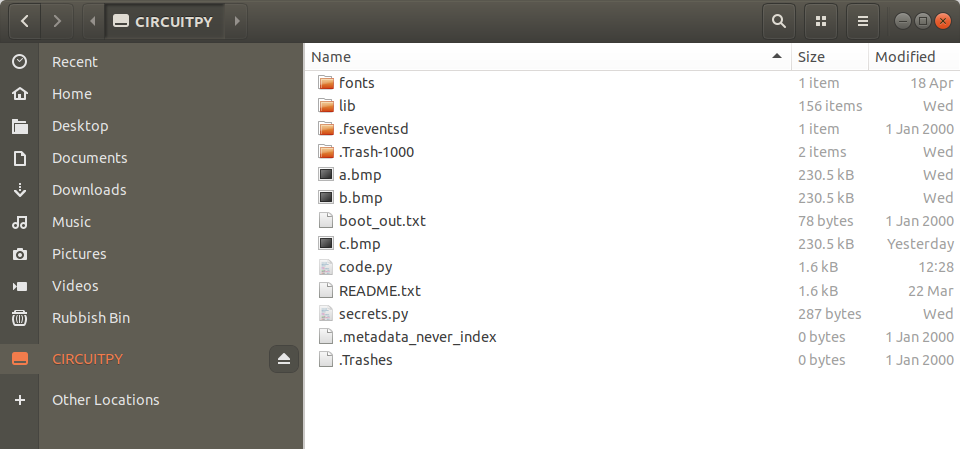
Now copy the images to the root of the CIRCUITPY drive.
Optional step - Generate a QR code
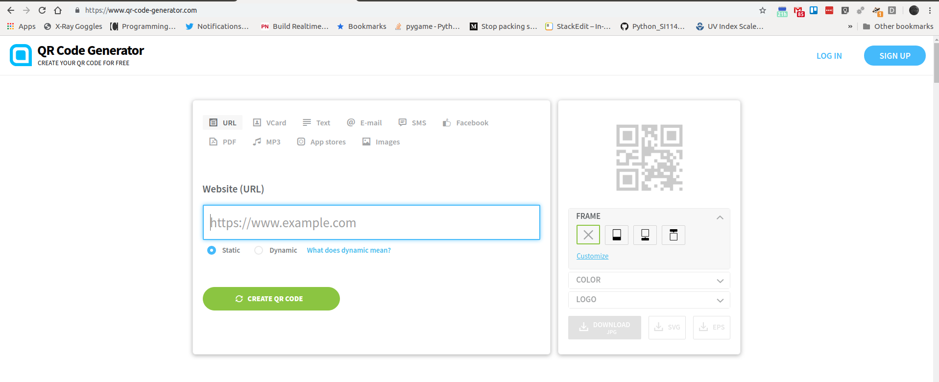
To create a VCard QR code I used this website which is free and easy to use.
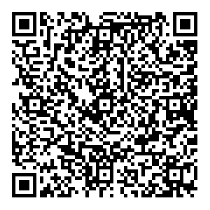
So I entered my details, set the colour of the QR code to black, so there is a high contrast on the screen. I downloaded the JPG. edited it in GIMP so that it fit correctly on the PyPortal screen and then copied it across as c.bmp
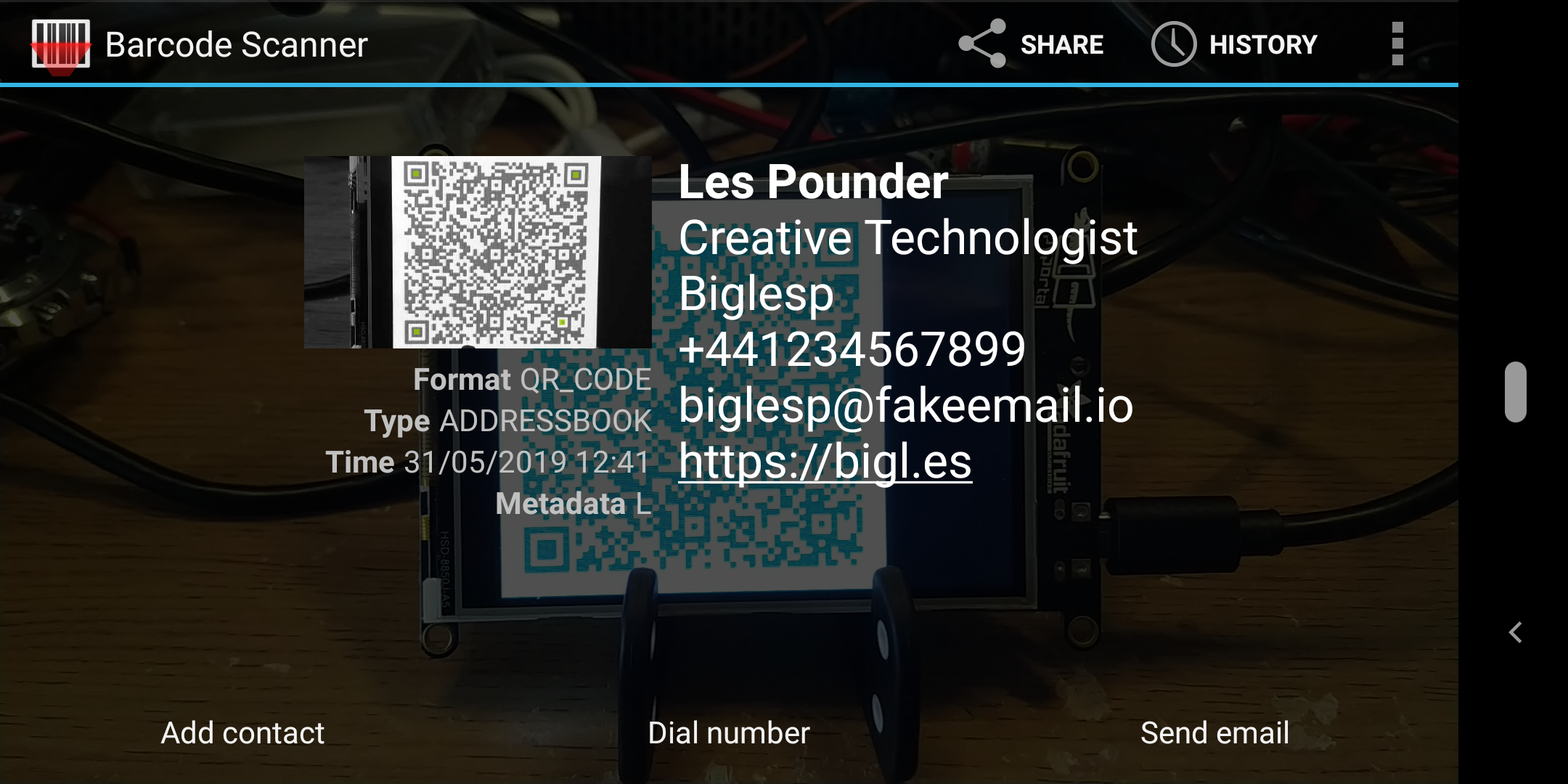
So when I scan the code I see this in my Barcode Scanner app.
Project Complete!
So now we can navigate around the images on our badge and show interested parties our latest projects, contact details, cat pictures. The final step would be to attach a lanyard and USB battery to the badge, this I shall leave up to you.
We have learnt
- How to write code for PyPortal using CircuitPython
- How to edit images for use on the screen
- How to use lists, dictionaries and tuples to store data
- How to react to input