Friday Fun - Hacking Poundland Halloween Electronics
Poundland is a favourite haunt of mine...as it contains lots of interesting things that can be hacked. From craft materials, garden supplies (slug tape is ace for cardboard circuits) to cheap "crappy" electronics.
Did Les say crappy electronics?
Yup! Poundland has excellent cheap electronics, the kind that kids love but adults hate because they are loud and bothersome.
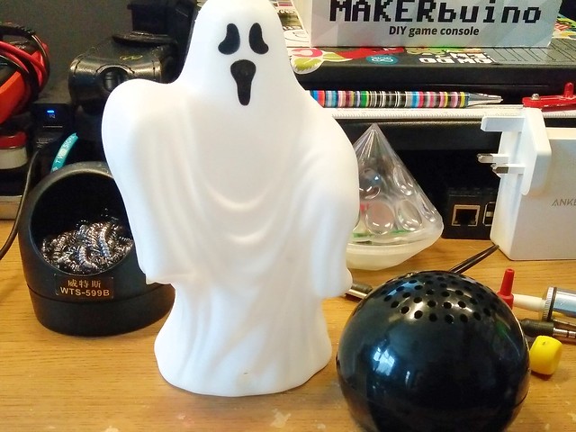
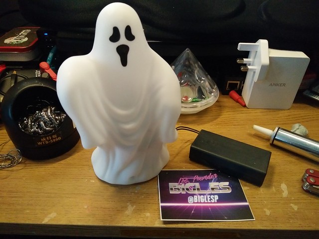
For example this ghost...

and this witch

Are exceptionally easy to hack. They both have a Light Dependent Resistor (LDR) that is used as a simple motion sensor.
When the witch / ghost is powered up, it takes a light level reading and then when the light level gets darker, for example when a hapless victim walks past, the creature comes to life and scares the victim. Well it tries to, but the speaker inside the ghost / witch is a bit pants. So we need an amplifier and better speaker...
Luckily Poundland have them too.
Does that speaker look familiar? Well it should as in a previous post we tore one apart.
Oh and we need a battery box, for 2 x AA batteries..wonder where we can get that from?

So why don't we hack them?
Yup you read that right, lets combine these three components to build a scarier, noisier ghost that will +guarantee maximum candy retention.
+ The retention of candy is not guaranteed by this website, nor from biglesp. Your candy levels may vary, if symptoms persist seek a dentist.
For this project you will need
From Poundland / Dollar Store
- A motion sensing witch / ghost
- A speaker / amp
- Any lights that run from 2 x AA batteries
- 2 x AA batteries
From your stock
- Soldering equipment
- Wire strippers and cutters
- Cross head screwdriver
- A multimeter
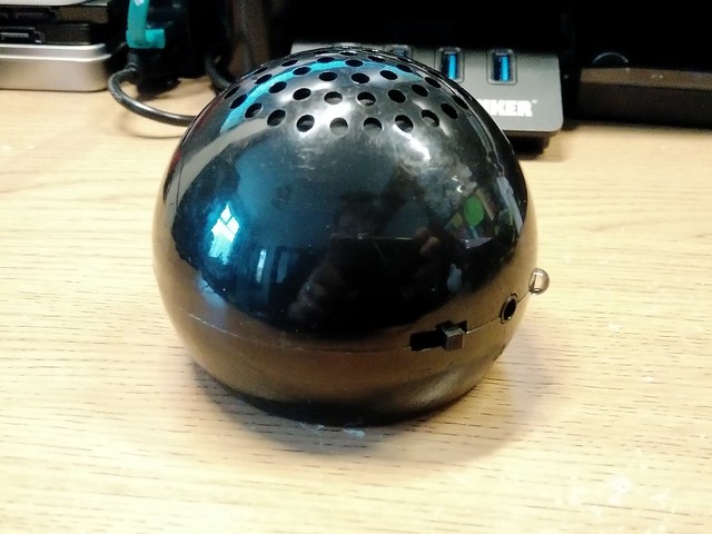
Teardown - The Speaker!
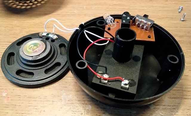
To get inside the speaker we need to unscrew 3 x cross head screws and gently pull the top off the speaker. You will see that the speaker is connected to the circuit board via two wires. Be careful not to break any wires.
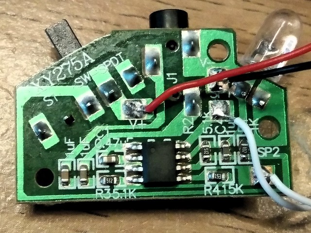
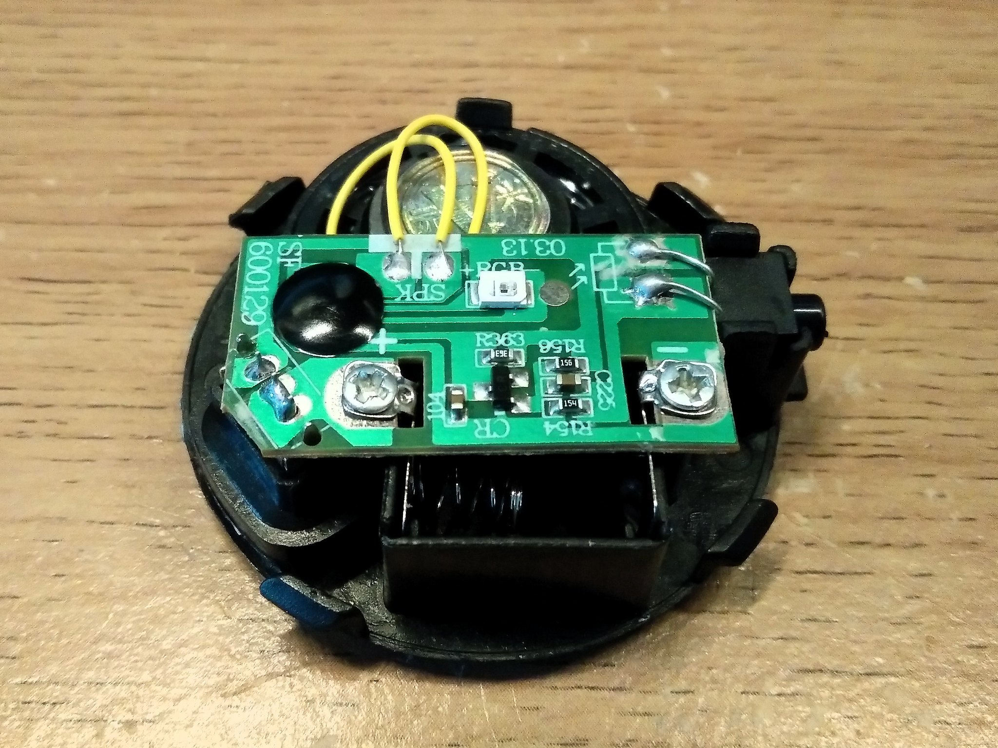
Inside the speaker there is a small PCB (Printed Circuit Board) which contains the components that will amplify the audio.
We are interested in
V+ Connects to the + battery terminal (Red wire)
V- Connects to the - battery terminal (Black wire)
So we need to desolder the wires from the V+ and V- contacts on the PCB and from the battery holder on the speaker. Be careful, and save the wires!
Creating a new battery box
Our amplifier / speaker needs power, and as we can't use the original battery box for the speaker, as it was the entire bottom half of the plastic shell, we need to create a new power source. For this we shall use the Poundland Halloween lights.
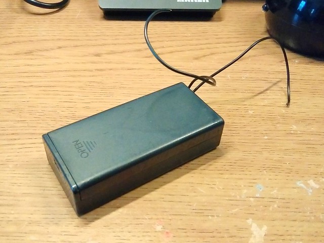
Chop the battery box from the lights, give yourself a good 15cm (6 inches) of wire from the battery box, as we need some spare length to run the battery box outside the witch / ghost.
With the battery box cut free, we next need to strip around 5mm of the plastic sleeving from the wires and then gently twist each wire so that they are neat. Then using a soldering iron we need to tin (apply a thin layer of solder) the exposed wires so that they do not unravel.
Once the wires have been tinned, we next need to turn our attention to the V+ and V- terminals on the speaker PCB. Flow a little solder on to these terminals, then put the soldering iron back in the holder!
Why are we flowing solder on to V+ and V-? They have some already!
True, but old solder can be dry and crusty looking, adding just a little fresh solder means the terminals will be easier to solder to.
So now that we have done a little soldering, we next need to determine the polarity of the battery box. We next need to insert 2 x AA batteries in the battery box, then set our multimeter to measure DC voltage (The letter V with a straight line) Then turn on the battery box, and lastly connect the wires of the battery box to the probes of your multimeter.
If the polarity is correct, then you will see a positive number, hopefully around 2.9 to 3.0V.
If the number is negative, then we have the wires the wrong way round, no big issue right now, but swap them around, and re-test.
Once you have found the correct polarity, mark the wire using some tape (masking tape is ideal as we can write on it) so that you know which is + and what is -.
Top tip: The positive wire (+) of the battery box connects to the switch. The negative (-) wire connects directly to the batteries. Follow the wires to confirm where they go.
Now remove the batteries from the battery box, and solder the wires, observing the correct polarity, to the V+ and V- terminals.
With the soldering complete, now re-insert the batteries and flick the swtich on the battery box and the speaker PCB. The LED should light up, confirming it is working!
Ghostbusters! - Hacking the ghost!
The ghost and the witch both have identical circuit boards. And to get access to them we need to gently pull the figure apart, you may need a flat blade screwdriver or a spudger to open the case.
Once the electronics are out, we can see two screw terminals marked + and -. These are the power connections, but the figure already has batteries, but not enough for this project. Unscrew the terminals and remove the cell batteries. Save them for a future project.
Parents / Teachers: Coin cell batteries are dangerous for children, if swallowed they can do some serious damage, requiring a trip to A&E. If working with a child, make sure that that the batteries are stored safely, or disposed of as per your local authorities recycling programme.
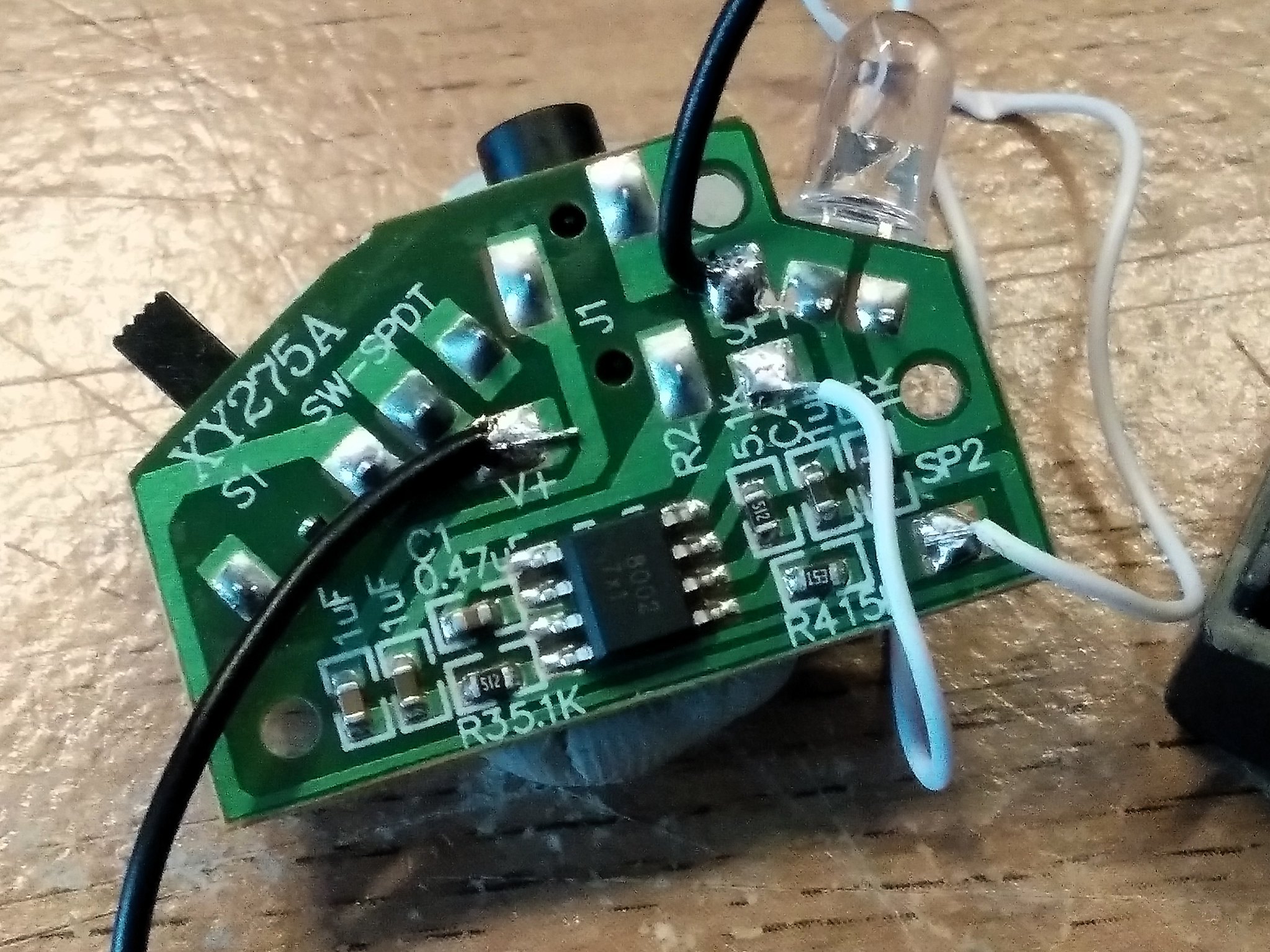
Now leave the screws off, and add a little solder to the + and - terminals, also remove the wires from the SPK terminals by desoldering them. Add a little fresh solder to the SPK terminals to make desoldering a little easier.
Remember the wires that we desoldered from the speaker battery box? You did save them? We shall use them to connect the output of our ghost / witch to the input of our speaker PCB.
For reference:
Speaker PCB Connections
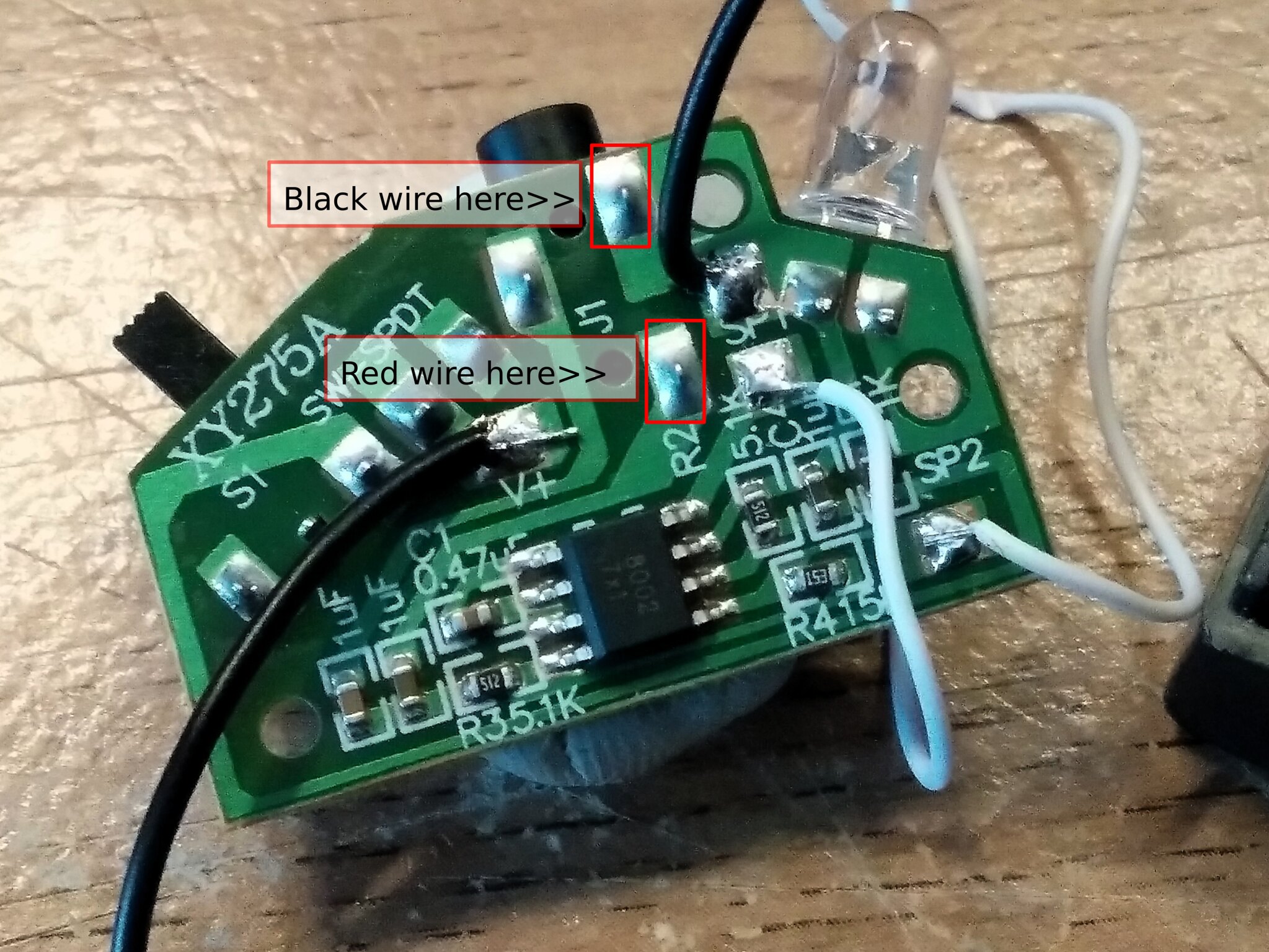
Ghost PCB Connections
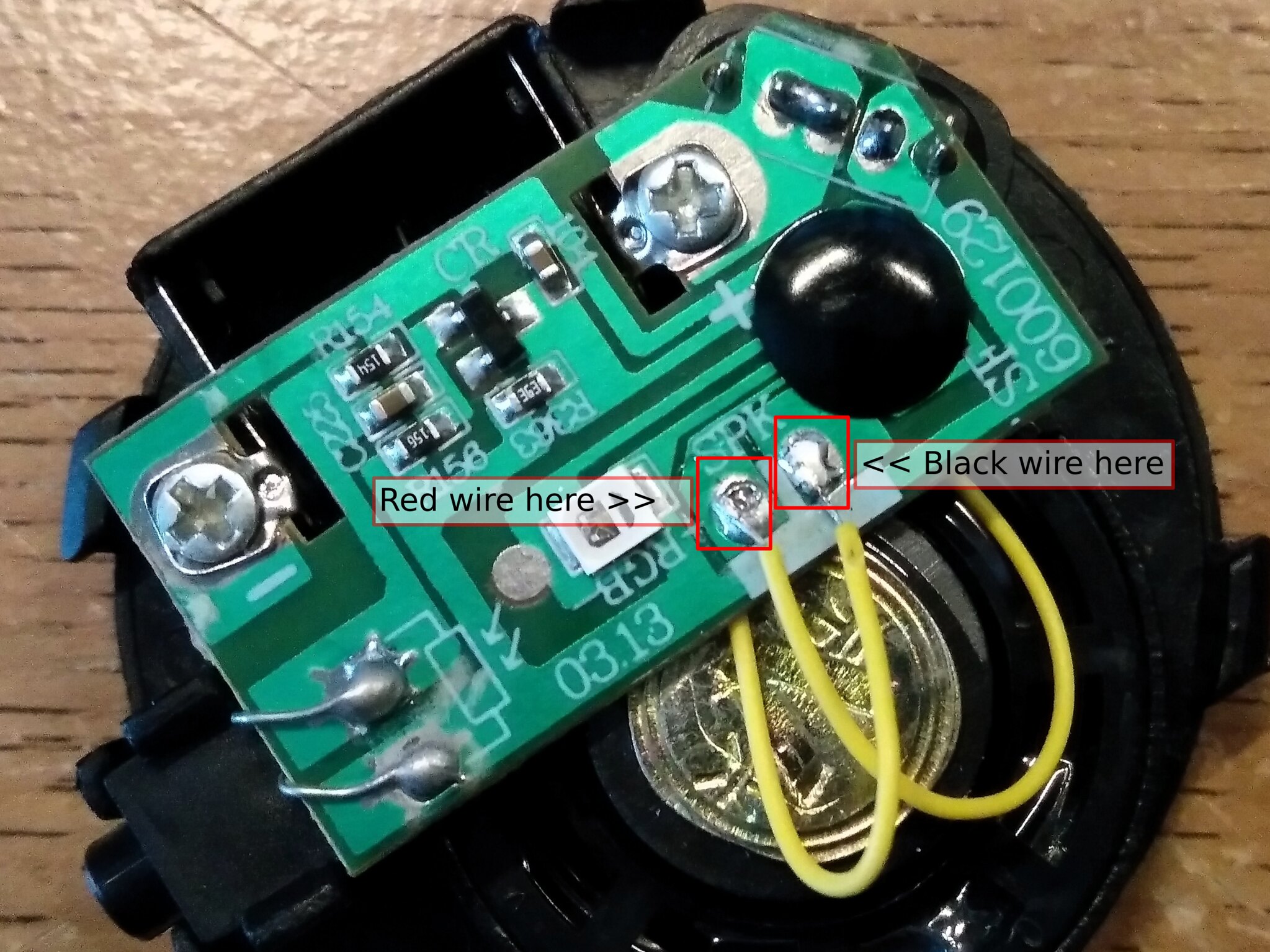
The Black Wire connects SPK terminal next to the black "blob" on the ghost PCB, to the speaker connection at the edge of the speaker PCB board board. It is a heavy section of solder, so flow some fresh solder.
The Red Wire connects the SPK terminal next to the RGB LED on the ghost PCB to the heavy soldered terminal next to "R2" on the speaker PCB.
The final part! Powering the ghost!
Our ghost / witch needs power! For this we need to solder a tinned wire from the + and - terminals of the ghost/witch PCB to the = and - terminals on the speaker PCB. This will share the power from the battery box with the speaker PCB and the ghost PCB.
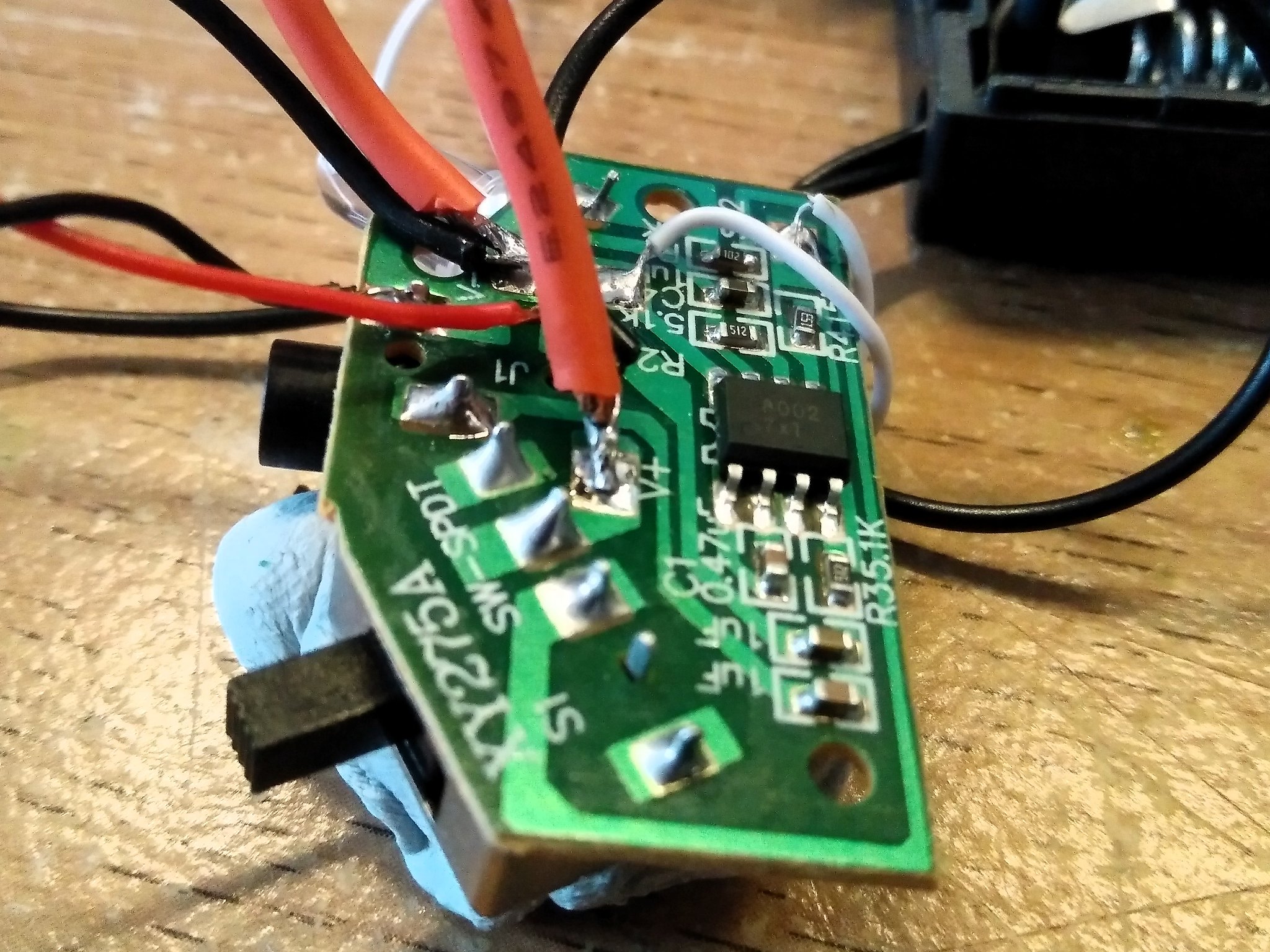
This will mean soldering wires on to the same pads as we soldered our power connections earlier. So it might be tricky as some wires might move out of place / come off. Be patient and take it slowly :)
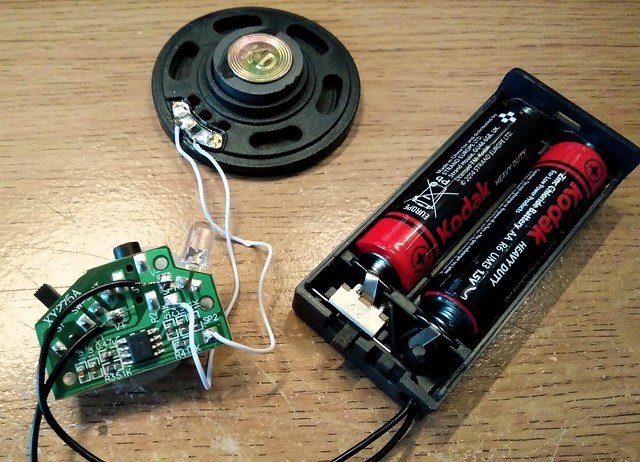
Completed soldering!
Your project should look like this!
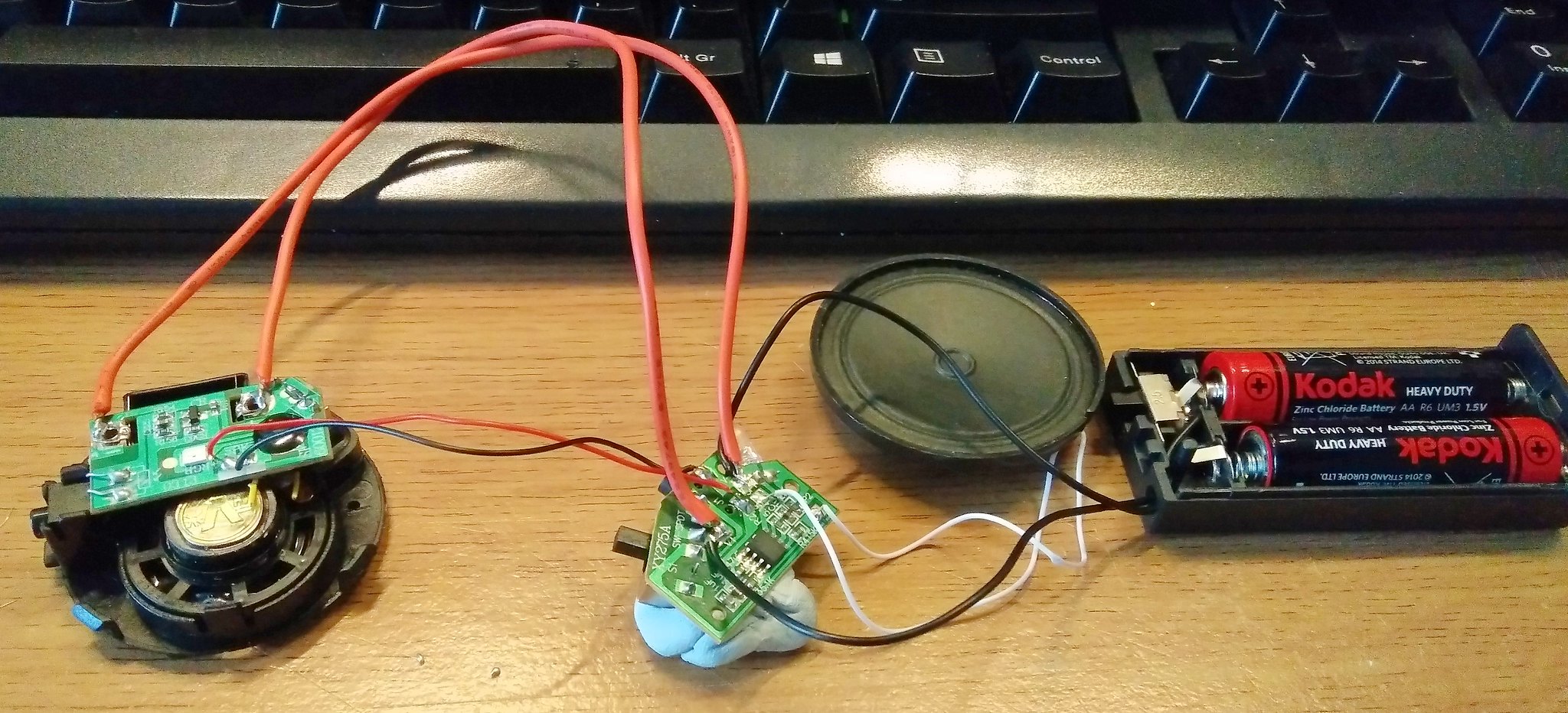
Now we just need to wrap the circuits in a little tape to stop them shorting each other out. Then stuff it all back inside the ghost!
Oh and because we all love a good video!
So what did we learn?
- We created something new using only £4 in parts.
- We learnt how to solder connections, and desolder old connections.
- We understood that our components needed a single power source.
- We developed a project that required no code, rather we augmented the design of the original product (ghost/witch) with other existing products.
- We learnt about polarity.